


 English
  عربى
عربى  中文简体
中文简体
Reminder information

May 15, 2026
Content
A Casing And Tubing Coupling Bucking Unit Lathe is a specialized industrial machine designed to assemble (make-up) and disassemble (break-out) threaded couplings onto oilfield tubulars with extreme precision. The core conclusion for any operator is that these units are essential for maintaining the structural integrity of the well string; by utilizing synchronized hydraulic power and high-resolution torque-turn monitoring, the ** ensures that every joint meets the strict API 5CT standards, preventing costly downhole leaks and mechanical failures.
The operation of a Casing And Tubing Coupling Bucking Unit Lathe revolves around the controlled application of rotational force. Unlike a standard metalworking lathe, this unit features a hydraulic power head and a secondary backup vise. The backup vise grips the pipe body securely while the power head rotates the coupling. This dual-clamping system prevents the pipe from spinning, ensuring that 100% of the hydraulic energy is converted into threading torque.
Advanced models incorporate a variable-speed drive system. This allows the machine to start at a high RPM for rapid threading (spinning) and then automatically switch to a low-RPM, high-torque mode for the final "shoulder" engagement. This transition is critical to avoid galling—a form of wear caused by excessive friction that can weld threads together prematurely.
Modern oilfield operations demand more than just physical strength; they require data validation. The ** is typically equipped with a Torque-Turn Control System. This computer-integrated setup measures the torque applied against the number of turns completed. By plotting these metrics on a graph in real-time, the unit can detect if the coupling has reached the optimum "sweet spot" of the thread profile.
A major challenge in pipe handling is avoiding "bite marks" or structural deformation of the casing. High-grade alloys used in deep-water wells are particularly sensitive to surface damage. The Casing And Tubing Coupling Bucking Unit Lathe addresses this through non-marking dies or specialized multi-point clamping systems.
| Clamp Type | Operational Advantage | Suitable Application |
| Standard Tooth Die | High-friction grip for heavy-duty torque. | Carbon steel casing and tubing. |
| Non-Marking Jaw | Smooth contact surface prevents stress risers. | Chrome and high-alloy CRA materials. |
| Floating Power Head | Compensates for thread lead variations. | Premium connections (gas-tight seals). |
| Synchronized Chuck | Applies equal pressure across the circumference. | Thin-walled tubulars prone to crushing. |
The integration of automation into the ** has significantly improved workshop safety. Traditional manual tongs require personnel to be in the "line of fire." In contrast, a bucking unit lathe allows the operator to control the entire make-up process from a remote console. Automation also ensures consistency; a machine does not suffer from the fatigue that can lead to inconsistent make-up torque over a long shift.
Hydraulic backups and emergency stop circuits are standard safety features. Furthermore, many units now feature automatic pipe loading and unloading arms, which synchronize with the lathe to move heavy joints (often weighing thousands of pounds) without manual lifting, reducing the risk of workplace injuries.
To ensure the Casing And Tubing Coupling Bucking Unit Lathe remains accurate, regular calibration of the load cells and hydraulic pressure transducers is mandatory. Over time, hydraulic seals can wear, leading to pressure drops that result in under-torqued joints.
Related Products
 Model:TYSK-630T Drill Pipe, Joint & Coupling Lathe
The machine adopts a FANUC CNC system with stable processing accuracy and flexible programming functions to ensure that the processed parts meet strict industry standards. The high torque and heavy-load design can cope with long-term continuous work and has strong durability.
 Model:TYSK-1355 Oil Pipe Processing Lathe
The machine adopts a FANUC CNC system with stable processing accuracy and flexible programming functions to ensure that the processed parts meet strict industry standards. The high torque and heavy-load design can cope with long-term continuous work and has strong durability.
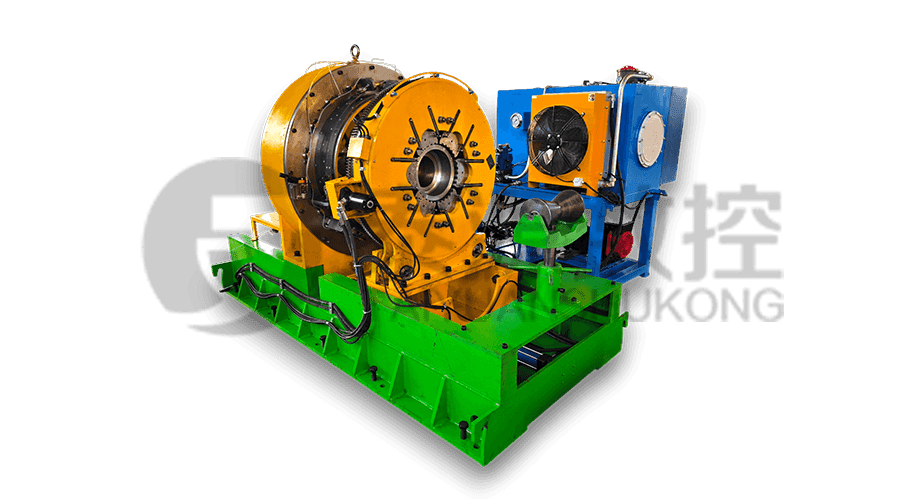
 Series:TYSK-NKJ Screw-on machine/Casing and tubing coupling bucking unit
The machine uses a hydraulic motor, mechanical floating mechanism, and real-time torque detection, adapts to material bending, and prevents material deformation. Auxiliary machines are configured to help with semi-automation.
 Long, heavy material solutions Automatic loading and unloading mechanism for pipe threading
The special flexible support mode can effectively reduce the influence of workpiece bending on processing and improve the yield. Strictly matching with our pipe threading lathe.
 Modular Iron Chip Crusher High strength crusher for chip
The blades are made of high-strength materials and reasonably placed at the exit of the chip extractor to break the clump iron chips.Reduce the risk of rollback and improve waste frame utilization.
 Series:TYSK-HB Semi-automatic wear-resistant band welder
Applicable to ARNCO 100XT, 200XT, 300XT. Support φ1.2-2.0 cored or solid wire surfacing welding.Can be equipped with single gun spray welding and double gun spray welding two ways. Support PLC or CNC system control.
 Model:TYSK-XQJ-550 Medium & Large PTFE Film Skiving Machine
Designed to process blanks with a maximum diameter of 550 mm and a maximum length of 1000 mm. We can also customize according to the needs of users. Friendly change speed and thickness with CNC.
