



 English
 عربى
 中文简体

Reminder information


Nov 06, 2026
Content
Evaluating a CNC pipe threading lathe comes down to two separate tests: whether it can hold thread geometry across a batch, and whether it can cut the pipe sizes, thread forms, and volumes you actually sell. A brochure maximum diameter proves neither. Ask for a witnessed test cut on your material, using the same thread form and workholding, with measurements taken on the first part, after warm-up, and at the end of the run.
Working definition: Machining accuracy is the lathe's ability to reproduce the specified thread geometry - pitch diameter, lead, flank angle, taper, thread length, and surface finish - within tolerance over consecutive parts. Thread processing capacity is the production envelope: pipe or coupling OD, length, weight, thread type, tooling, cycle time, and automation. The two are related, but they are not interchangeable.
A lathe with a large swing but a short thread stroke can look capable on a specification sheet while still needing a repositioning step on a long casing thread. Check the work envelope against the actual part drawing, not against a headline number.
Accuracy on a pipe threading lathe is not one number. It is the combined result of spindle and chuck runout, guideway and ballscrew condition, servo response, tool path, workpiece support, thermal growth, and the thread insert or tool. The most useful evidence is a dimensional report from a test cut, supported by static geometry records.
Measure pitch diameter, lead error over the full thread length, flank angle, taper, thread length, roundness, and surface finish. For oilfield casing and tubing, API 5B thread gauging practice and API 5CT product requirements are common references; confirm the exact edition and thread form specified by the buyer. A gauge that accepts the thread does not by itself prove that the machine can repeat the result over a shift.
| Check | What it reveals | Evidence to request |
|---|---|---|
| Spindle and chuck runout | Transfers into thread eccentricity and wall-thickness variation; check the workholding interface, not only the spindle taper. | Runout record at the chuck jaws and a test-bar report. |
| Lead and pitch error | Changes flank contact and gauge fit; inspect over the full thread length and at more than one spindle speed. | Lead measurement trace and gauge results. |
| Flank angle and thread form | Determines whether the specified API or premium connection gauge accepts the thread; insert geometry and compensation must match. | Thread profile trace, insert specification, and gauge report. |
| Taper and alignment | Affects standoff and coupling make-up; check tailstock and steady-rest alignment on a production-length part. | Taper measurement on the same length and support condition. |
| Repeatability and drift | A machine that holds size cold but moves after warm-up can split a batch. | First-part, warm-up, and end-of-run records with time stamps. |
| Surface finish and chatter | Rough flanks increase gauge uncertainty and can hide pitch errors, especially at long overhang. | Roughness values, cutting parameters, and a cut on the worst overhang. |
Before the cut, ask for runout at the chuck jaws, guideway straightness, ballscrew backlash, and tailstock or steady-rest alignment. These checks show where error can enter before cutting force and heat are applied, and they help explain why one lathe holds size while another needs constant offsets.
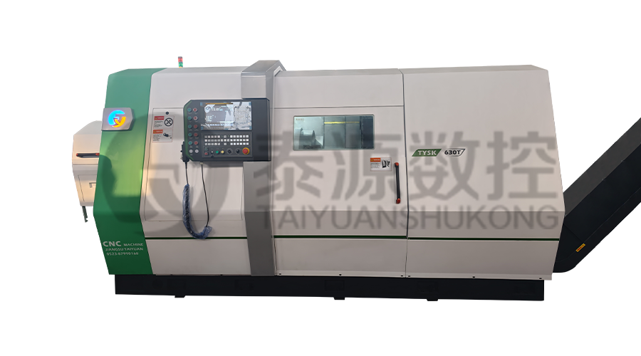 CNC Pipe Threading Lathes and Pipe-Processing EquipmentReview CNC pipe threading lathes and related equipment, including featured FANUC-controlled models, before matching spindle bore and capacity to pipe work.View Product →
Capacity is the production envelope, not the largest pipe the lathe can swing. A machine may accept a large OD but lack the spindle bore, steady rest, thread length, torque, or chip control to cut the required wall thickness at a stable cycle time. Confirm spindle bore and through-hole clearance against the longest and heaviest pipe in the quotation, not just the nominal diameter.
| Capacity item | Why it matters | What to verify |
|---|---|---|
| Work envelope | Pipe OD, coupling OD, length, weight, swing, spindle bore, chuck, steady rest, and tailstock support must all fit the part. | Dimensioned envelope drawing and workholding layout. |
| Thread range | API 8-round, buttress, premium, straight or tapered threads, TPI or pitch range, thread length, and hand of thread. | Thread program list and sample parts. |
| Material and wall thickness | Carbon steel, low-alloy, stainless, and high-strength pipe change cutting force, tool wear, and cycle time. | A cutting trial on your material grade and wall. |
| Tooling and gauges | Insert or tool availability, setup time, gauge compatibility, and spare-part support affect repeatability. | Tooling list, gauge plan, and recommended spares. |
| Cycle time | Handling, alignment, roughing, finishing, gauging, and chip removal all count toward the production rate. | Element-by-element cycle time sheet from a timed run. |
| Automation and chip control | Loading, unloading, coolant delivery, chip evacuation, and interlocks decide whether the machine sustains output. | Automation layout and a production-run sample. |
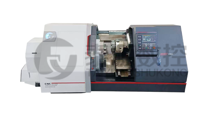 TYSK-1355 Oil Pipe Processing LatheFANUC-controlled lathe for oil casing, couplings, and drill pipe repair, with Φ1000 mm range, customizable spindle bore, and heavy-load design.View Product →
Use the same sequence for every supplier so the comparison stays like-for-like.
Buyers often compare a tighter machine with a heavier, faster machine. The right balance depends on thread form, wall thickness, and batch pattern, not on a single accuracy number.
Put the evaluation in writing so the quotation and acceptance test measure the same thing.
Illustrative example. A fabricator plans to cut API 8-round threads on 5-1/2 in casing couplings. Two lathes have similar swing. Supplier A offers a short test cut in mild steel; Supplier B offers a timed run on the same casing grade, with pitch-diameter and lead records at first part, after warm-up, and at the end of the run. Supplier B's proposal gives the buyer a basis to compare gauge fit, drift, and cycle time. Supplier A's offer leaves the main batch risk unresolved. This is a hypothetical scenario, not a customer project.
A defensible evaluation ends with four documents: a drawing-specific work envelope, a test-cut measurement record, a gauge and tooling plan, and an acceptance procedure tied to your production batch. If a supplier cannot provide those for the thread you actually buy, the accuracy claim is still an assumption.
Related Products
Model:TYSK-630T Drill Pipe, Joint & Coupling Lathe
The machine adopts a FANUC CNC system with stable processing accuracy and flexible programming functions to ensure that the processed parts meet strict industry standards. The high torque and heavy-load design can cope with long-term continuous work and has strong durability.
Model:TYSK-1355 Oil Pipe Processing Lathe
The machine adopts a FANUC CNC system with stable processing accuracy and flexible programming functions to ensure that the processed parts meet strict industry standards. The high torque and heavy-load design can cope with long-term continuous work and has strong durability.
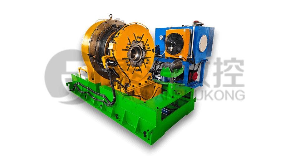 Series:TYSK-NKJ Screw-on machine/Casing and tubing coupling bucking unit
The machine uses a hydraulic motor, mechanical floating mechanism, and real-time torque detection, adapts to material bending, and prevents material deformation. Auxiliary machines are configured to help with semi-automation.
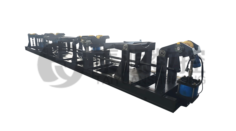 Long, heavy material solutions Automatic loading and unloading mechanism for pipe threading
The special flexible support mode can effectively reduce the influence of workpiece bending on processing and improve the yield. Strictly matching with our pipe threading lathe.
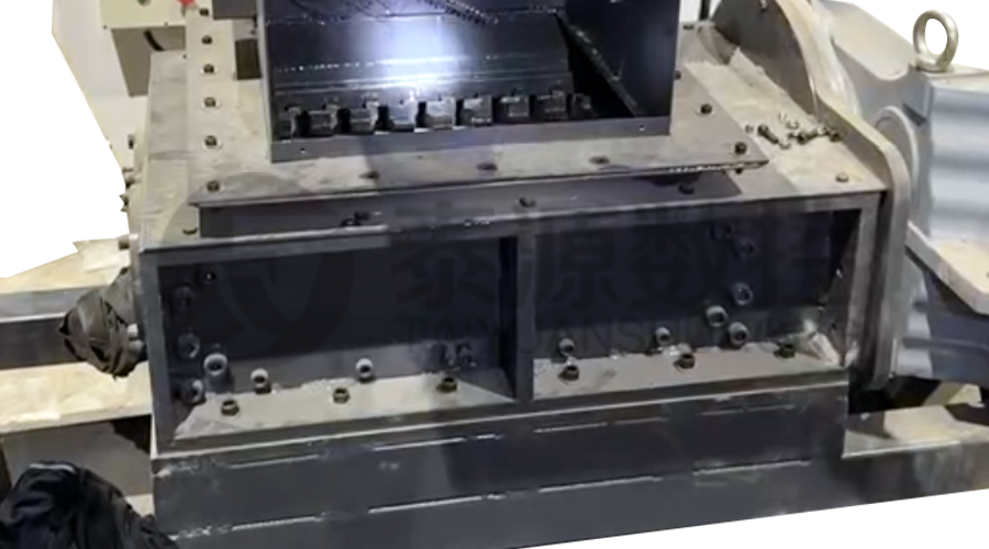 Modular Iron Chip Crusher High strength crusher for chip
The blades are made of high-strength materials and reasonably placed at the exit of the chip extractor to break the clump iron chips.Reduce the risk of rollback and improve waste frame utilization.
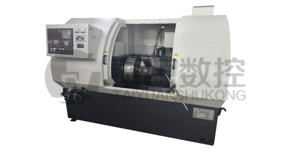 Series:TYSK-HB Semi-automatic wear-resistant band welder
Applicable to ARNCO 100XT, 200XT, 300XT. Support φ1.2-2.0 cored or solid wire surfacing welding.Can be equipped with single gun spray welding and double gun spray welding two ways. Support PLC or CNC system control.
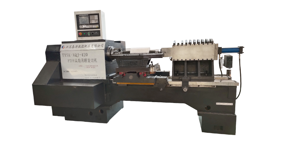 Model:TYSK-XQJ-550 Medium & Large PTFE Film Skiving Machine
Designed to process blanks with a maximum diameter of 550 mm and a maximum length of 1000 mm. We can also customize according to the needs of users. Friendly change speed and thickness with CNC.
