



 English
 عربى
 中文简体

Reminder information


Nov 04, 2026
Content
Most drill pipe and coupling lines are planned around a lathe purchase and then run into trouble at the station nobody sized properly: the bucking unit, the hard banding torch, or the handling between operations. Output on an oilfield pipe processing line is set by the slowest station and by how much work-in-process is waiting in front of it, not by the number of machines on the quotation.
The decisions that matter come in a fixed order: the workpiece envelope you must cover, the process route each part follows, the ability of each machine to hold thread geometry, and the way pipes move and are inspected between operations. Handle those four and the line can absorb new pipe sizes later; skip them and adding machines rarely fixes the throughput problem.
Equipment selection starts with the dimensions you must produce: pipe body outside diameter and wall thickness, tool joint outside diameter including any hard banding allowance, finished length, thread form, and the coupling stock that pairs with each pipe size.
Drill pipe and couplings may share one building, but they do not share one machining logic. A pipe body arrives long and slender and has to be supported along its length; a coupling is short and stiff and produced in batches. The same lathe rarely serves both well, and the layout has to move material between the two families without stacking it in a corridor.
| Requirement | Drill pipe | Coupling |
|---|---|---|
| Workpiece length | Pipe body of several metres, carried on roller steady rests | Short part, handled and gauged in batches |
| Governing machine dimension | Spindle bore, through-hole length and steady rest capacity | Chuck size, bore depth and shoulder face access |
| Critical geometry | Pin and box thread concentricity with the pipe axis | Thread alignment at both ends of the same part |
| Fixturing | Chuck plus steady rests, low runout at the thread end | Short-overhang fixture, fast load and unload |
| Typical quality gate | Thread gauging, shoulder contact, hydrostatic test | Thread gauging before make-up, torque-turn record |
Write the envelope as a matrix that covers your current catalogue and the sizes you expect to quote over the next three to five years. A machine that only fits today's largest joint becomes a production constraint the first time a customer asks for a bigger connection.
A drill pipe line and a coupling line overlap at the threading machines but diverge before and after them, so the first layout decision is which operations you keep in-house and which you buy as finished parts.
For drill pipe, a workable route runs as follows:
Couplings follow a shorter route: cut coupling stock to length, face and bore, cut internal threads at both ends, gauge, phosphate, then make up onto the pipe at the bucking station. The two routes meet at the gauging bench and final inspection, which is why a shared inspection area belongs between them rather than at the far end of the building.
The threading lathe decides both thread quality and the achievable cycle time, so its specification should be written around the largest pipe outside diameter and the tightest thread tolerance you will produce, not around the average job.
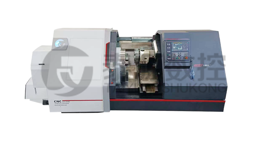 TYSK-1355 CNC Oil Pipe Processing LatheReview this oil pipe threading lathe for API and premium-connection work, with FANUC control and claimed accuracy, rigidity and efficiency.View Product →
Four parameters carry most of the risk. Spindle bore must pass the pipe body with clearance for the chuck jaws and any coating thickness. Through-hole length and steady rest capacity decide how much of the pipe hangs outside the machine and how much deflection you accept at the cutting zone. Spindle torque at threading speed affects surface finish and tool life on large-diameter joints. Thread pitch accuracy and taper adjustment decide whether the connection passes gauging without rework.
Ask for pitch error accumulation over the full thread length rather than a single-pitch figure, and confirm how the shoulder face is machined relative to the thread axis. On larger pipe the shoulder is the load-bearing and sealing surface, and a shoulder cut out of square shows up as a leak path or a rejected connection long after the lathe has been accepted. A machine sized in the 1000 mm bore class can cover casing and tubing work as well as larger drill pipe joints, but confirm the actual bore, chuck and steady rest limits against your own envelope before treating it as a general-purpose asset.
Tool joints and couplings are short, stiff parts, so the constraint shifts from bore size to shoulder squareness, thread flank finish and repeatable load and unload time.
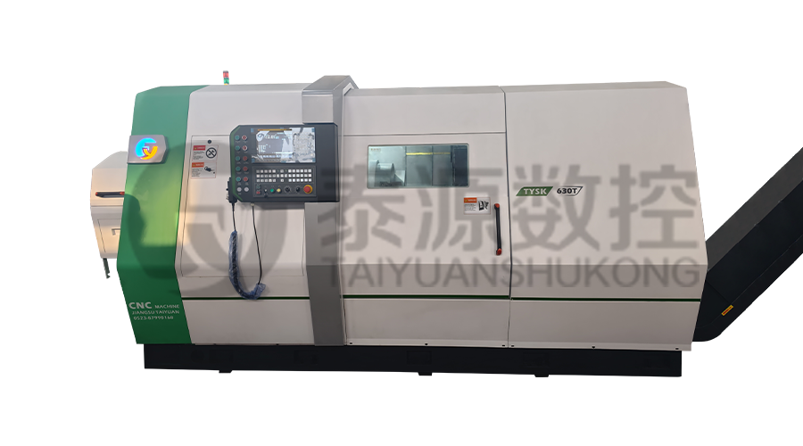 TYSK-630T Drill Pipe Joint and Coupling LatheCheck this FANUC-controlled lathe for short, stiff joint and coupling work where shoulder squareness, thread finish and repeatable loading matter.View Product →
A dedicated joint and coupling lathe with a shorter bed and higher spindle speed usually beats a long pipe lathe on these parts, because the cycle is dominated by handling and by the number of passes on a hardened forging rather than by reach. Confirm how the machine holds the forging, whether the fixture references the thread axis or the outside diameter, and how long a size changeover takes when you move from one connection type to another. For couplings produced in batches, tool change time and the ability to gauge at the machine matter as much as spindle speed.
Make-up is a controlled assembly operation, not a tightening step. A bucking unit applies torque until the mating shoulders meet, and the torque-turn curve shows whether the shoulder actually engaged before the target torque was reached.
When specifying a screw-on bucking unit, confirm the torque range and how torque is measured: a load cell arrangement behaves differently from a pressure-derived estimate, particularly at the low end of the range. Ask about calibration procedure, torque-turn recording, and the time needed to change from one pipe size to another. A unit that needs half a shift for a size change will be avoided by the operators, and the workaround is usually a torque value nobody can trace.
Hard banding is welded onto the tool joint outside diameter to reduce casing wear and tool joint wear, and it adds a second heat input to a part that has already been welded, heat treated and threaded.
Decide early whether banding runs in line or off line. In line, it can become the bottleneck because deposition rate is limited and the band usually needs machining afterwards to control finished diameter. Off line, it adds handling and a second queue. Whichever you choose, specify preheat, band thickness tolerance, the alloy family and whether the finished band must be machined flush. Casing-friendly alloys reduce wear on the casing but wear the tool joint faster, so the choice follows the application rather than a general preference.
Automation pays back where pipe handling, not cutting, dominates the cycle. On long pipe work, loading, positioning, steady rest adjustment and unloading can consume more time than the thread itself.
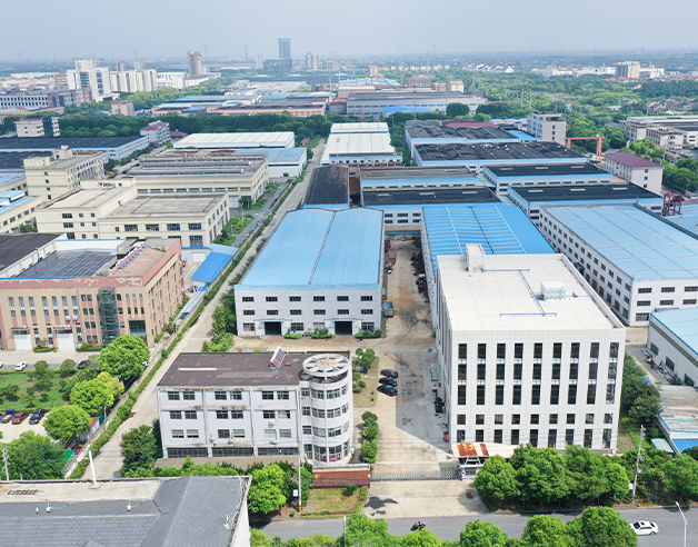 Drill Pipe Joint Production LineExplore the manufacturer’s drill pipe joint production line and related grinding, threading and inspection equipment for oilfield, geological and mining applications.View Product →
Look for loading and unloading mechanisms that reference the pipe consistently, because repeatable positioning is what allows a single operator to run two or three machines. In-process gauging at the machine reduces the distance a suspect thread travels before it is caught. Chip handling is easy to underestimate: turning pipe ends and tool joint forgings produces long, stringy chips that bridge in conveyors and jam coolant lines. A chip conveyor paired with a crusher, plus coolant filtration sized for the volume of swarf, prevents the stoppages that quietly erase the gains from automation.
A line is balanced when every station's available capacity, after changeovers and planned downtime, exceeds demand by a margin you have chosen deliberately.
The figures below are an illustrative example, not measured data from any installation. They show how the arithmetic works before equipment is ordered.
| Station | Cycle time (min per piece) | Theoretical output (pcs/h) | At 85% availability (pcs/h) | Meets 12 pcs/h |
|---|---|---|---|---|
| Thread turning | 5.0 | 12.0 | 10.2 | No |
| Bucking | 3.0 | 20.0 | 17.0 | Yes |
| Hard banding | 6.0 | 10.0 | 8.5 | No |
| Gauging and inspection | 2.5 | 24.0 | 20.4 | Yes |
In this hypothetical case the threading lathe sits exactly on the demand line with no buffer, so any tool change pushes it below target, and hard banding is the real bottleneck. The usual options are a second threading machine, a faster banding head, or moving banding off the critical path. The availability figure should come from your own equipment history, including tool changes, gauging stops and shift handovers; substituting a round 85% without checking it is how capacity plans go wrong.
Inspection should sit where it stops scrap from advancing, not only at final inspection. Buyers working to API Spec 5DP for drill pipe, API Spec 5CT for casing and tubing, API Spec 5B for casing and tubing thread dimensions, and API Spec 7-2 for rotary shouldered connection gauging will expect records that match the standard they are buying against.
Practical gates are incoming verification of heat number and mechanical properties, first-piece thread gauging at the start of every batch, in-process pitch diameter and taper checks, shoulder contact pattern before make-up, torque-turn records from the bucking unit, and hydrostatic test records by serial number. Keeping gauges and records near the machine also shortens the loop between detection and correction, which matters more on a line than in a job shop. A broader overview of drill pipe standards for construction and maintenance is useful when writing the inspection plan.
Machine quotations are only comparable when the enquiry describes the same scope. Include the following before asking for prices:
Suppliers who answer the envelope and acceptance sections specifically, with gaps named rather than hidden, tend to be easier to hold to a schedule after the order.
An efficient drill pipe and coupling line is an exercise in sequence rather than in machine count. Fix the envelope, write the route, size every station against the same demand figure, and place inspection where it prevents scrap from travelling. Equipment can be added later; a layout that ignores material flow cannot be corrected cheaply.
Related Products
Model:TYSK-630T Drill Pipe, Joint & Coupling Lathe
The machine adopts a FANUC CNC system with stable processing accuracy and flexible programming functions to ensure that the processed parts meet strict industry standards. The high torque and heavy-load design can cope with long-term continuous work and has strong durability.
Model:TYSK-1355 Oil Pipe Processing Lathe
The machine adopts a FANUC CNC system with stable processing accuracy and flexible programming functions to ensure that the processed parts meet strict industry standards. The high torque and heavy-load design can cope with long-term continuous work and has strong durability.
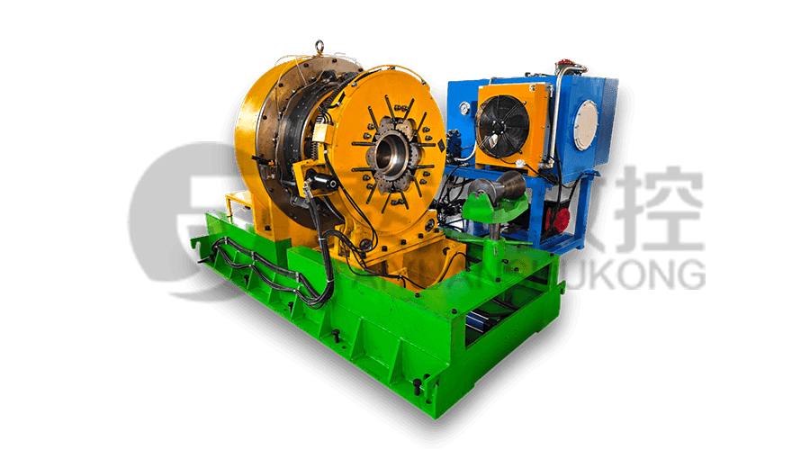 Series:TYSK-NKJ Screw-on machine/Casing and tubing coupling bucking unit
The machine uses a hydraulic motor, mechanical floating mechanism, and real-time torque detection, adapts to material bending, and prevents material deformation. Auxiliary machines are configured to help with semi-automation.
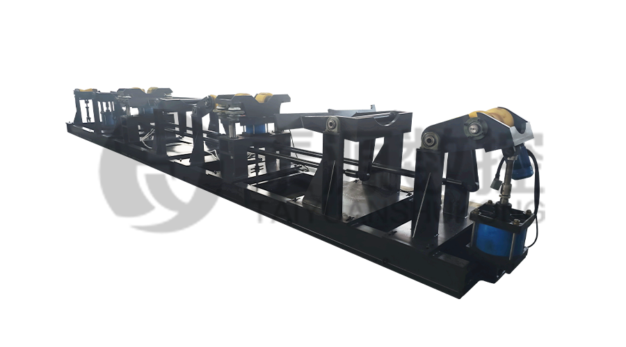 Long, heavy material solutions Automatic loading and unloading mechanism for pipe threading
The special flexible support mode can effectively reduce the influence of workpiece bending on processing and improve the yield. Strictly matching with our pipe threading lathe.
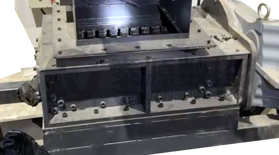 Modular Iron Chip Crusher High strength crusher for chip
The blades are made of high-strength materials and reasonably placed at the exit of the chip extractor to break the clump iron chips.Reduce the risk of rollback and improve waste frame utilization.
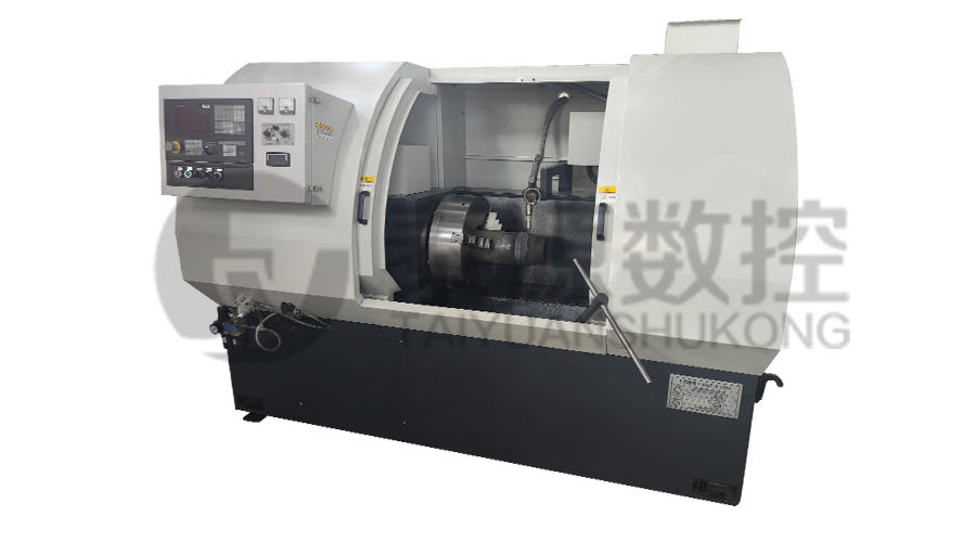 Series:TYSK-HB Semi-automatic wear-resistant band welder
Applicable to ARNCO 100XT, 200XT, 300XT. Support φ1.2-2.0 cored or solid wire surfacing welding.Can be equipped with single gun spray welding and double gun spray welding two ways. Support PLC or CNC system control.
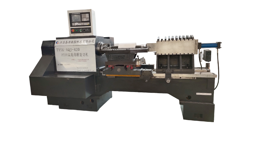 Model:TYSK-XQJ-550 Medium & Large PTFE Film Skiving Machine
Designed to process blanks with a maximum diameter of 550 mm and a maximum length of 1000 mm. We can also customize according to the needs of users. Friendly change speed and thickness with CNC.
