



 English
 عربى
 中文简体

Reminder information


Oct 30, 2026
Content
Put a ring gauge on the first coupling that comes off a new lathe and it will almost always pass. Run that same machine for four hours on P110 heavy-wall casing and the picture changes: pitch diameter drifts toward the limit, thread crests begin to tear, and the operator quietly trims the feed to hold tolerance. The distance between a good first part and a stable thousandth part is what you are really buying.
So here is the conclusion first. Evaluate machining accuracy as a capability measured across a run of consecutive parts cut from your own pipe with your own gauges. Evaluate production efficiency as minutes per accepted part, with loading, clamping, gauging, chip removal and rework all counted in. A positioning accuracy figure of a few microns proves almost nothing about either number; a forty-part capability run and one timed shift prove nearly everything.
The rest of this article sets out the checks that turn both claims into evidence you can hold a supplier to.
Casing, tubing and drill pipe joints live or die by thread form. On a coupling or pin threaded to API 5CT and 5B practice, the features that decide whether the joint seals and makes up to torque are the same features you should measure at acceptance:
One setup part proves that an operator can dial a machine in. A consecutive-part run proves that the machine holds. Ask for thirty to fifty parts threaded without touching offsets, and ask for the measurement records in the same format your incoming inspection uses. If a supplier cannot describe how those records are kept for standard gauging, take it as a warning: the discipline behind API 5CT compliance on a casing and tubing bucking lathe is the same discipline your acceptance protocol depends on.
Two failure modes show up after installation rather than before it: thermal drift and deflection under heavy cut. Both are easy to expose in a single day if the test is designed for it.
Compare the cold and warm groups. A drift of more than a small fraction of your thread tolerance band across a shift means the machine will need offset corrections many times a day, and that cost lands on your operators rather than on the supplier.
| Indicator you are shown | What it genuinely shows | What it can hide |
|---|---|---|
| X and Z axis positioning accuracy | Control and drive quality under light, unloaded conditions | Thermal growth and deflection during a heavy interrupted cut |
| One good part measured on a setup piece | The operator can dial the machine in | Batch spread, tool wear rate and offset drift across a shift |
| Roundness of a test bar | Spindle and chuck condition at low load | Chatter risk when the tool engages forged or heavy-wall pipe |
| Pitch diameter checked with a ring gauge | Local thread form conformance | Taper, lead error and standoff over a long thread length |
| Cycle time read from the control | Programmed motion time only | Loading, clamping, gauging, chip clearing and rework time |
Cycle time on the control screen flatters every machine. It counts programmed motion and assumes the part is good. The honest metric is total floor time divided by accepted parts, because that is the number your costing sheet eventually absorbs.
An example. Suppose a coupling takes six minutes of cutting and two minutes of loading and clamping, and one part in twenty needs four minutes of rework. The real figure is not eight minutes; it is about 8.2 minutes per good part, and it worsens every time a gauge check turns into an offset change. Cutting handling time through automation moves that number by roughly a fifth. Halving rework moves it further, and neither improvement requires a faster spindle.
That is why a machine sized and configured for pipe work usually beats a general-purpose lathe pushed into the same job. A model built around a large through-bore, a chuck sized for casing, and a control set up for threading cycles starts from a better baseline.
| Cycle element | Typical share of floor time | How to verify it before you buy |
|---|---|---|
| Cutting time per thread | Roughly a third to a half | Time a run on your grade and wall thickness with tool changes included |
| Load, clamp and unload | A fifth to two fifths on manual machines | Time the full sequence with your heaviest pipe |
| In-process gauging and offset changes | Five to fifteen percent | Count how often the operator leaves the machine per part |
| Chip removal and swarf handling | Rarely measured until it stops the line | Run a full shift and watch conveyor and crusher loading |
| Rework and scrap | Two to ten percent when a process drifts | Ask for the scrap rate from the last month of production |
The through-bore sets the largest pipe the machine can pass and the rigidity you keep at working diameter. A bore that is only just big enough forces long overhang, and overhang is where chatter and taper error come from. Match the bore to the largest casing or drill pipe you expect to run in the next five years, not to the average of last year's work.
On manual pipe lathes, handling is often a third of the cycle. Powered chucks, steady rests and roller supports at floor level cut that time without touching a single cutting parameter. Where volume justifies it, a dedicated loading and unloading mechanism removes the operator from the heaviest part of the cycle and keeps cycle time consistent through a full shift instead of only for the first two hours.
Heavy-wall turning produces long, stringy chips that wrap around the tool, stall conveyors and force manual basket changes. A chip breaker paired with a crusher that reduces stringy swarf to uniform chips keeps evacuation moving and removes a cleaning task that rarely appears in cycle time studies but always appears in shift logs.
If you also make up and break out couplings, torque control is an accuracy issue as much as an efficiency one. What matters in practice is repeatable torque output, fast changeover between casing sizes, and the ability to hold shoulder standoff under load rather than only on a light test joint.
Most disputes over oilfield machine tools come from acceptance wording, not from the iron itself. Cover these points before the purchase order is signed:
These clauses cost nothing to negotiate before signature and are difficult to add afterwards.
Two numbers carry the decision: the spread of dimensions across a long run, and the minutes per accepted part on your own material. Everything else on a specification sheet is supporting detail. A machine that holds the first number and improves the second is worth its price, whatever positioning accuracy figure happens to be printed beside it.
Related Products
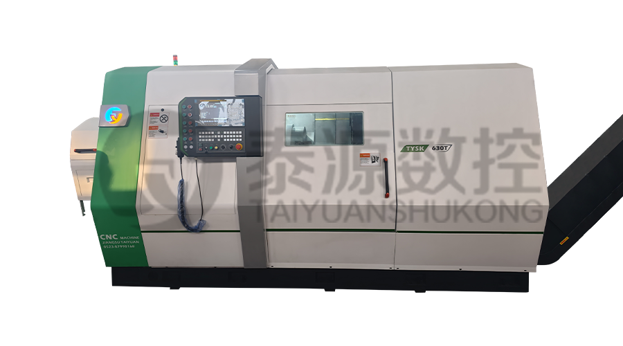 Model:TYSK-630T Drill Pipe, Joint & Coupling Lathe
The machine adopts a FANUC CNC system with stable processing accuracy and flexible programming functions to ensure that the processed parts meet strict industry standards. The high torque and heavy-load design can cope with long-term continuous work and has strong durability.
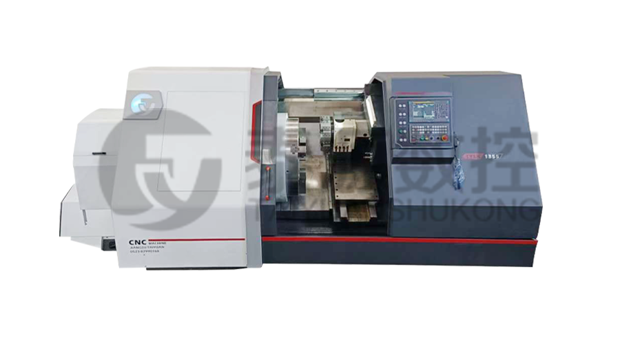 Model:TYSK-1355 Oil Pipe Processing Lathe
The machine adopts a FANUC CNC system with stable processing accuracy and flexible programming functions to ensure that the processed parts meet strict industry standards. The high torque and heavy-load design can cope with long-term continuous work and has strong durability.
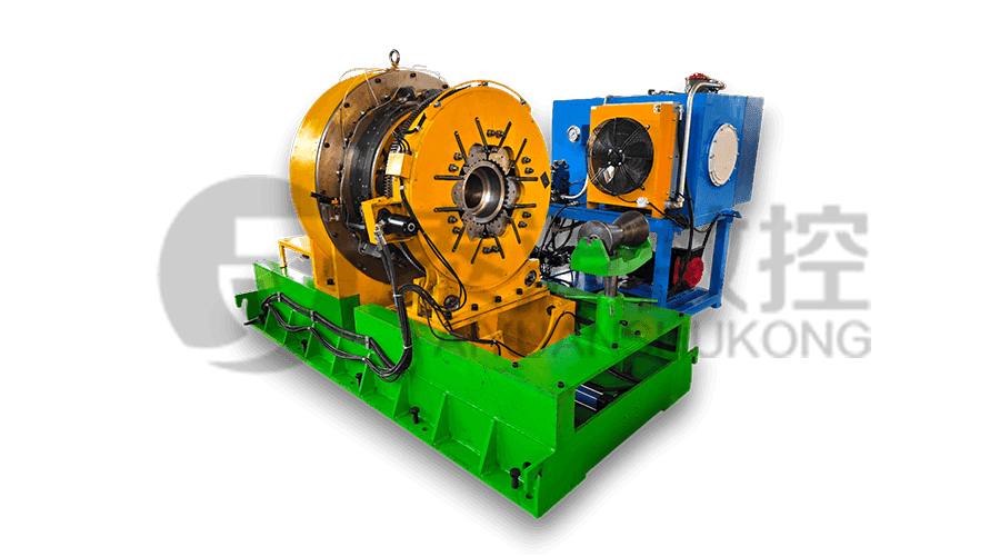 Series:TYSK-NKJ Screw-on machine/Casing and tubing coupling bucking unit
The machine uses a hydraulic motor, mechanical floating mechanism, and real-time torque detection, adapts to material bending, and prevents material deformation. Auxiliary machines are configured to help with semi-automation.
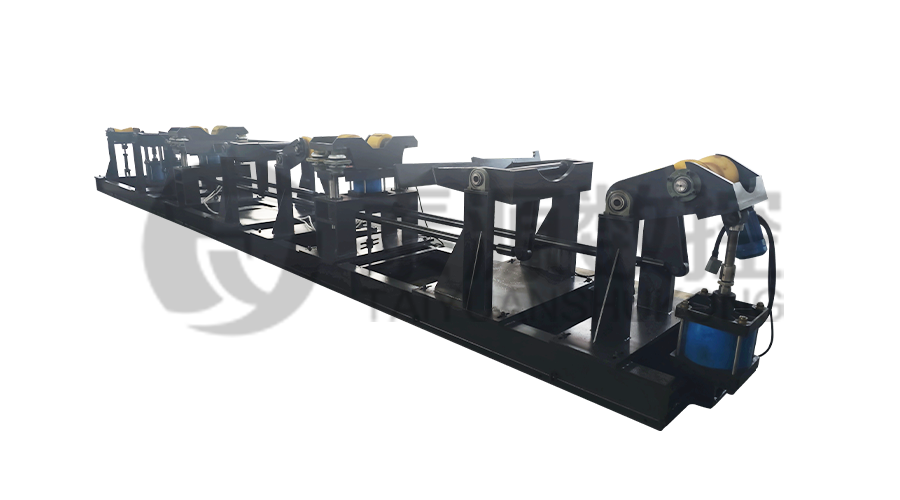 Long, heavy material solutions Automatic loading and unloading mechanism for pipe threading
The special flexible support mode can effectively reduce the influence of workpiece bending on processing and improve the yield. Strictly matching with our pipe threading lathe.
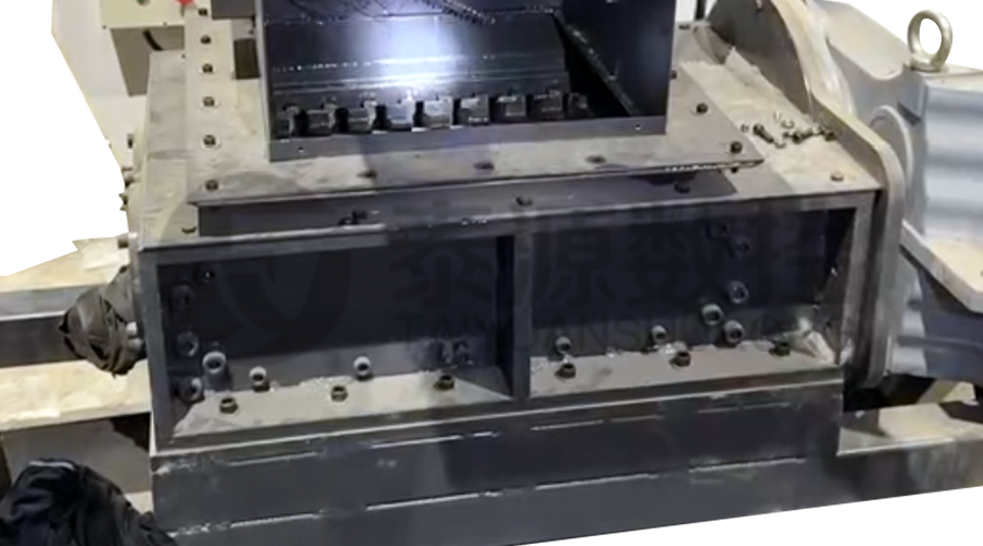 Modular Iron Chip Crusher High strength crusher for chip
The blades are made of high-strength materials and reasonably placed at the exit of the chip extractor to break the clump iron chips.Reduce the risk of rollback and improve waste frame utilization.
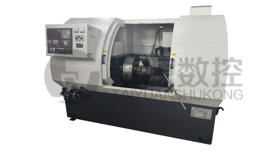 Series:TYSK-HB Semi-automatic wear-resistant band welder
Applicable to ARNCO 100XT, 200XT, 300XT. Support φ1.2-2.0 cored or solid wire surfacing welding.Can be equipped with single gun spray welding and double gun spray welding two ways. Support PLC or CNC system control.
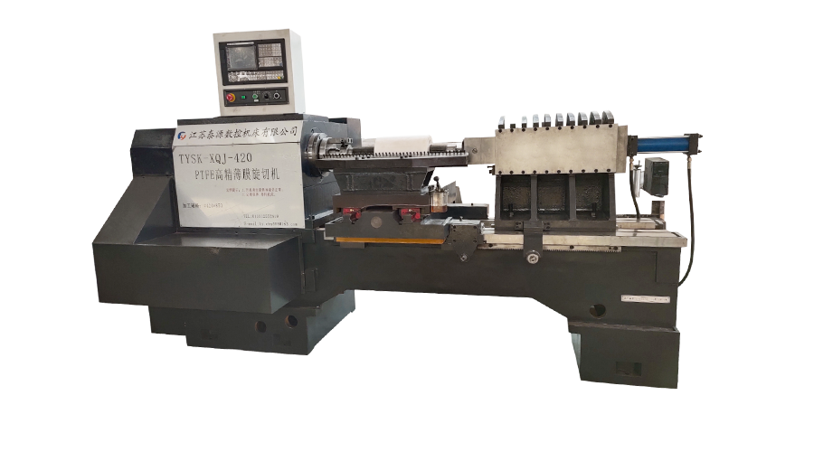 Model:TYSK-XQJ-550 Medium & Large PTFE Film Skiving Machine
Designed to process blanks with a maximum diameter of 550 mm and a maximum length of 1000 mm. We can also customize according to the needs of users. Friendly change speed and thickness with CNC.
