



 English
 عربى
 中文简体

Reminder information

Oct 23, 2026
Content
A wiped pin on a 5 1/2 in drill pipe arrives in the repair bay with three problems at once: galled thread crests, a shoulder face brinelled by the power tong, and a tool joint OD that no longer runs true. The tube itself is fine. The real question is whether the shop can recut the connection and return it to full torque, or whether the joint has to be cut off and replaced.
Reliable thread restoration comes down to four equipment requirements. The machine needs enough clear bore and swing to take the tool joint. The spindle and threading axis must reproduce API taper, lead, and thread height accurately. Workholding has to centre a long tube without inducing runout. And the shop needs gauging that proves the finished connection. Control brand, automation level, and floor space are secondary. A shop that buys the largest lathe it can afford without checking those four points usually ends up with a machine that can turn pipe but cannot re-certify a connection.
Repair machining is a sequence of decisions rather than a single operation, and the failure modes that bring a joint into the shop are predictable.
Only two of those five items are thread problems in the narrow sense. A shoulder that will not seat, or a joint body worn oval, still fails after a perfect thread cut. That is why inspection comes first: pin length, shoulder width, OD at the band and at the shoulder, and a ring gauge check before any tool touches the part.
Once the joint is on the machine, the constraint is how much material can come off. Recutting a pin shortens the nose, and refacing a shoulder removes metal from the face. Every API connection carries a minimum pin base length, a minimum shoulder width, and a minimum remaining wall under the last engaged thread. Cross those limits and the joint is scrap, however good the surface finish looks.
Start with the largest tool joint OD in your inventory. The through-bore has to clear it with margin, because the tube either passes through the spindle and out the back, or it is supported by a steady rest ahead of the chuck.
| Drill pipe OD | Typical connection | Working minimum through-bore | Practical note |
|---|---|---|---|
| 2 3/8 in / 60.3 mm | NC26, 2 3/8 IF | about 110 mm | Often recut on a general CNC lathe with a steady rest |
| 2 7/8 in / 73.0 mm | NC31 | about 130 mm | Watch clearance at the box, not only the pin |
| 3 1/2 in / 88.9 mm | NC38, 3 1/2 IF | about 150 mm | Soft jaws bored to the tube OD are essential |
| 4 1/2 in / 114.3 mm | NC46 | about 190 mm | Steady rest position drives thread quality |
| 5 in / 127.0 mm | NC50 | about 215 mm | Most common size in mixed repair work |
| 5 1/2 in / 139.7 mm | NC56, 5 1/2 FH | about 240 mm | Check carriage clearance at the band |
| 6 5/8 in / 168.3 mm | NC70, 6 5/8 FH | about 290 mm | Machines in this class need floor space planning |
Those figures are planning targets rather than machine specifications. Measure the actual tool joint and box ODs you run, then add 15 to 20 mm of clearance. Swing over the bed matters for the same reason: the tool joint is the largest feature on the part and still has to clear the carriage and the steady rest pads.
Bed length catches people out. A joint lathe does not need to be 10 m long, because the tube is supported outside the machine, but it does need enough usable bed for a chuck, a steady rest, and a tool carriage to work without interference, which in practice means 1.5 to 2 m for single-end work. Machining both ends in one setup is a different problem, and usually pushes the shop toward two steadies or a cut-and-weld process.
Rotary shouldered connections are tapered threads, and the taper is not negotiable. API 7-2 defines the form, and the 1 in 6 taper used on most drill pipe connections has to be generated by the machine rather than approximated. Two failure patterns show up in shops that treat pipe threads like ordinary turning. The first is a thread that gauges correctly on a ring gauge but seats with the wrong standoff, which points to a shoulder face out of square or a drifting pitch diameter. The second is a thread that passes inspection and fails after fifty make-ups, which almost always traces back to crest truncation or root geometry.
What the machine has to deliver is a spindle encoder, a synchronised Z axis, a threading cycle with multiple spring passes, and enough rigidity that the tool does not deflect through the cut. Lead error accumulates along the thread, so a lathe that holds 0.01 mm on a 30 mm test bar may still produce an out-of-tolerance connection over a 90 mm thread length. Ask for a threading accuracy figure over the thread length you will actually cut. The material and process logic that governs new joint production applies equally to repair work, and is set out in our note on modern processing technology and material selection for drill pipe joint lathes.
Chatter is the enemy of a tapered thread. A joint held at one end with 9 m of tube hanging off the back behaves like a long spring, and any interruption in the cut shows up as a washboard pattern on the flanks. The practical countermeasures are a properly preloaded spindle, a steady rest placed as close to the joint as the tooling allows, soft jaws bored to the actual tube OD rather than a nominal size, and the shortest possible tool overhang.
Thermal drift deserves its own line in the specification. A spindle that has run for twenty minutes sits at a different temperature from a cold one, and over a long threaded connection that difference shows up in the pitch diameter reading. Establish a warm-up routine, cut a test thread at the start of each shift, and keep coolant temperature stable.
The joint is a heavy, long, slightly bent workpiece and cannot be gripped like a short shaft. Soft jaws or a compensating chuck clamping on the tube OD are the normal answer, positioned far enough back that jaw marks do not land on a sealing or load-bearing surface. Box-end work adds a boring requirement: a bar long enough to reach the box bottom, with the rigidity to hold size on an internal taper.
No lathe can prove a connection on its own. A complete repair cell includes ring and plug gauges for every connection size, a taper gauge, a lead gauge, a thread height comparator, and standoff measurement against a master gauge or a calibrated reference joint. Budget for them at the same time as the machine. A shop that inspects threads with a caliper and a pitch gauge is producing joints that fail somewhere it cannot see.
Many drill pipe repairs are more than thread repairs. When hardbanding has spalled or a band has to be replaced, welding joins the sequence, and the order of operations matters more than the equipment list. Strip the old band, confirm base material and preheat requirements, weld the new band, and only then re-establish the running surface.
Two things typically go wrong. Welding heat distorts the joint body, so a thread cut before the band is welded can end up with a runout error in the finished connection. And a band that is not concentric with the thread axis accelerates casing wear. The practical answer is to machine the band and the joint OD after welding, using the same chucking reference as the thread. A semi-automatic band welder with controlled dilution, consistent overlap, and repeatable preheat gives the machinist a uniform surface to cut, which is worth more than a small gain in deposition rate.
Three configurations turn up in repair shops, and they are not interchangeable.
| Configuration | Where it fits | Strength | Limit |
|---|---|---|---|
| Manual engine lathe with taper attachment | One-off and odd-size work | Low capital cost, flexible | Taper and lead depend on operator skill, hard to document |
| CNC pipe threading lathe with hollow spindle | Mixed repair, 2 3/8 in to 5 1/2 in | Repeatable threading cycle, programmable taper and pitch | Needs correct steady rest setup and clear bore sizing |
| Dedicated drill pipe joint coupling lathe | Regular pin and box end repair | Purpose-built workholding, fast changeover, consistent shoulder refacing | Higher capital cost, less flexible for unrelated work |
For a shop cutting a handful of joints a week, a CNC pipe threading lathe with an adequate bore and a well-set steady rest is the sensible entry point. When joint repair becomes production work, with pin and box ends both machined and hardbanding in the same flow, a dedicated joint lathe pays back through changeover time and consistency rather than through raw cutting speed. It is worth comparing configurations against the CNC machine tools for oil pipe and joint machining offered by builders who work in this field, because bore, swing, threading accuracy, and workholding are the four numbers that separate a general lathe from a repair machine.
Write the tender around the work, not around the machine catalogue.
Thread restoration is a measurement problem wearing the clothes of a machining problem. Decide which connection sizes you actually run, work out the clear bore and swing they demand, insist on a threading axis that holds lead and taper over the full thread length, and buy the gauges on the same purchase order as the machine. Do that, and a worn drill pipe joint leaves the shop indistinguishable from a new one at the gauge, which is the only standard that matters once the pipe goes back downhole.
Related Products
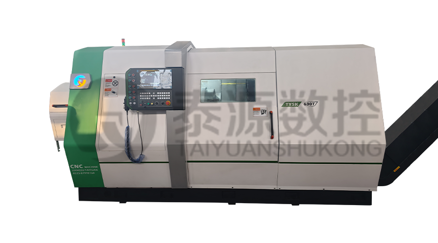 Model:TYSK-630T Drill Pipe, Joint & Coupling Lathe
The machine adopts a FANUC CNC system with stable processing accuracy and flexible programming functions to ensure that the processed parts meet strict industry standards. The high torque and heavy-load design can cope with long-term continuous work and has strong durability.
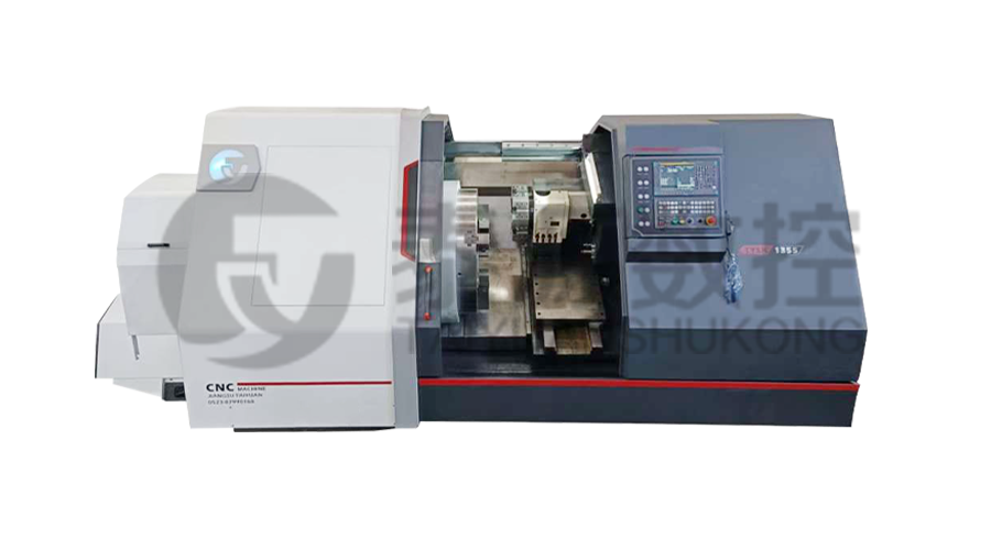 Model:TYSK-1355 Oil Pipe Processing Lathe
The machine adopts a FANUC CNC system with stable processing accuracy and flexible programming functions to ensure that the processed parts meet strict industry standards. The high torque and heavy-load design can cope with long-term continuous work and has strong durability.
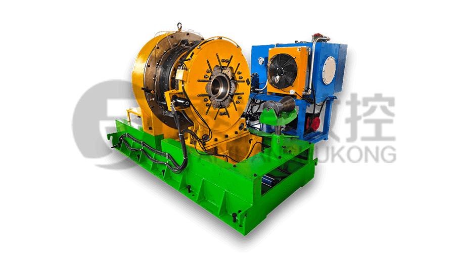 Series:TYSK-NKJ Screw-on machine/Casing and tubing coupling bucking unit
The machine uses a hydraulic motor, mechanical floating mechanism, and real-time torque detection, adapts to material bending, and prevents material deformation. Auxiliary machines are configured to help with semi-automation.
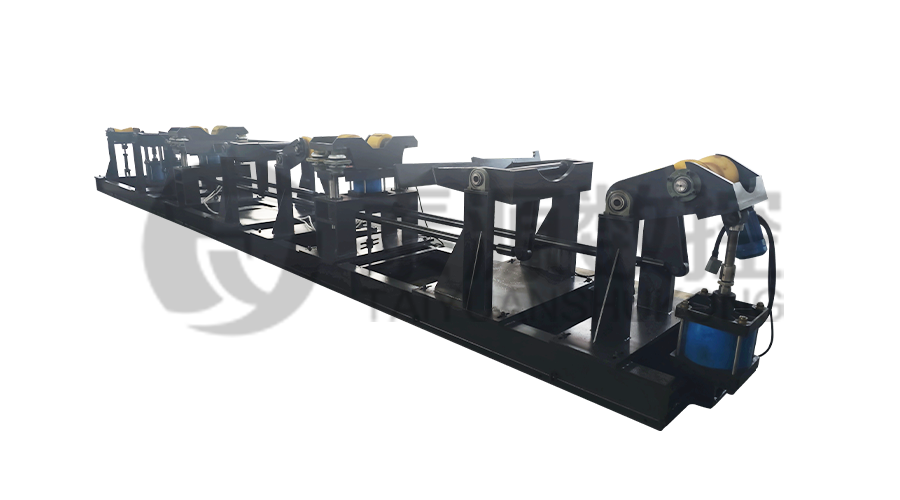 Long, heavy material solutions Automatic loading and unloading mechanism for pipe threading
The special flexible support mode can effectively reduce the influence of workpiece bending on processing and improve the yield. Strictly matching with our pipe threading lathe.
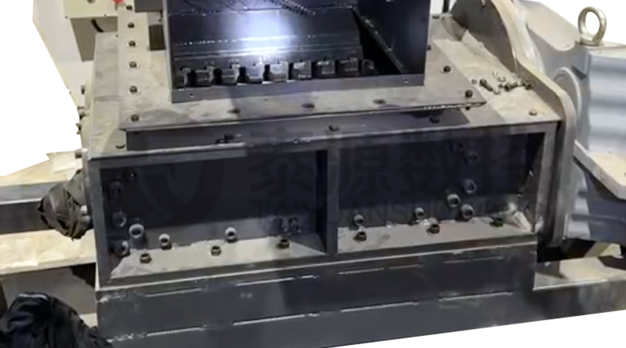 Modular Iron Chip Crusher High strength crusher for chip
The blades are made of high-strength materials and reasonably placed at the exit of the chip extractor to break the clump iron chips.Reduce the risk of rollback and improve waste frame utilization.
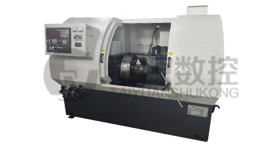 Series:TYSK-HB Semi-automatic wear-resistant band welder
Applicable to ARNCO 100XT, 200XT, 300XT. Support φ1.2-2.0 cored or solid wire surfacing welding.Can be equipped with single gun spray welding and double gun spray welding two ways. Support PLC or CNC system control.
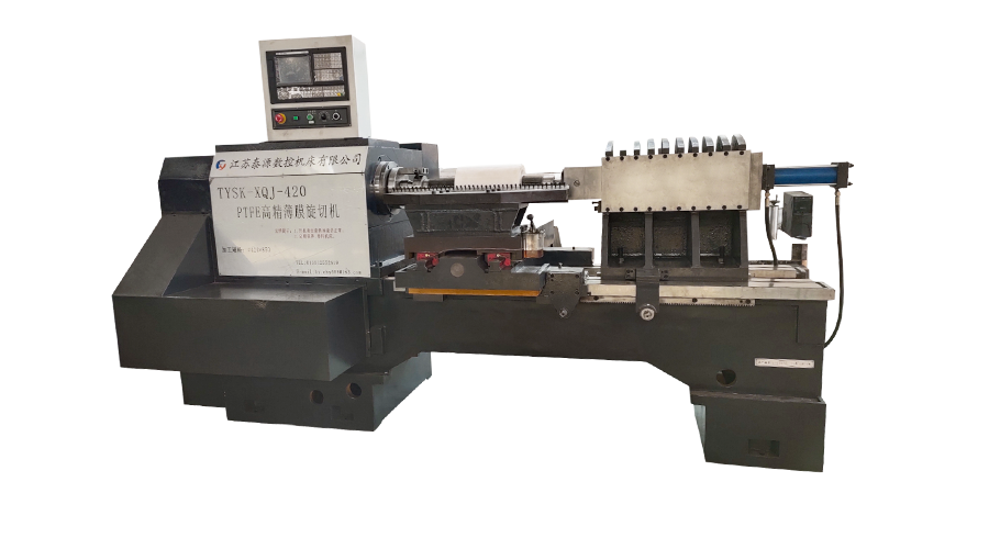 Model:TYSK-XQJ-550 Medium & Large PTFE Film Skiving Machine
Designed to process blanks with a maximum diameter of 550 mm and a maximum length of 1000 mm. We can also customize according to the needs of users. Friendly change speed and thickness with CNC.
