


 English
  عربى
عربى  中文简体
中文简体
Reminder information

Oct 17, 2025
Content
Precision threading is critical in pipe fabrication, yet many operators struggle with pitch errors and depth inconsistencies that compromise joint integrity. This comprehensive guide explores practical solutions for achieving perfect threads on your CNC pipe threading lathe, combining technical depth with actionable maintenance strategies.
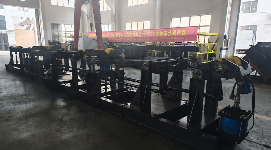
Φ1000mm Oil Pipe Processing Lathe Machine
Before addressing specific errors, operators must understand how thread geometry and machine kinematics interact. The relationship between tool path, material properties, and machine rigidity fundamentally determines threading accuracy.
Proper machine configuration forms the foundation for consistent threading results. These procedures apply universally to quality pipe threading equipment regardless of manufacturer.
Misalignment between workpiece and tool path creates compounding errors throughout the threading operation. Implementing rigorous alignment protocols prevents fundamental geometric defects.
Threading insert specifications directly influence pitch accuracy and surface finish. Understanding insert characteristics helps operators select optimal tools for their specific CNC threading lathe applications.
| Insert Type | Best Application | Pitch Accuracy | Tool Life |
| Full-form carbide | Standard thread profiles | Excellent | Medium |
| Partial-profile CBN | Hard materials | Good | Long |
| High-positive geometry | Stainless steels | Very Good | Short-Medium |
| Coated carbide | General purpose | Good | Long |
Pitch errors typically stem from mechanical backlash, thermal expansion, or programming inaccuracies. These advanced strategies address the root causes of pitch diameter miscalculation in production environments.
Mechanical slack in ball screws and drive systems creates non-linear tool movement that directly impacts pitch accuracy. Modern CNC systems provide sophisticated compensation methods.
Machine tools experience dimensional changes as components heat during operation. These thermal effects cause measurable pitch variation that requires active compensation strategies.
Uneven thread depth creates weak points in pipe connections and leads to premature failure. Addressing thread depth inconsistency requires systematic investigation of multiple machine systems.
Progressive tool wear creates gradual depth reduction that operators often miss until parts fall out of tolerance. Implementing robust tool monitoring prevents this drift.
Cutting forces inevitably cause pipe deflection, creating depth variation along the thread length. Understanding and compensating for this deflection is essential for solving pipe thread quality issues.
| Pipe Material | Typical Deflection (mm) | Compensation Strategy | Support Requirement |
| Carbon Steel | 0.05-0.15 | Programmed depth adjustment | Medium steady rests |
| Stainless Steel | 0.08-0.20 | Reduced feed rates + adjustment | Multiple steady rests |
| Alloy Steel | 0.10-0.25 | Multi-pass strategy + adjustment | Heavy-duty supports |
| Titanium | 0.15-0.30 | Conservative parameters + live adjustment | Rigid clamping system |
Modern CNC systems offer sophisticated programming options that can proactively prevent many common threading defects. Mastering these CNC threading parameters separates adequate operators from exceptional ones.
Single-pass threading creates excessive forces that promote deflection and tool pressure variations. Proper multi-pass strategies distribute cutting forces for consistent results.
Advanced CNC systems can monitor cutting conditions and automatically adjust parameters in real-time. This capability is particularly valuable for maintaining thread depth consistency when machining variable materials.
Even perfectly calibrated machines degrade over time without proper maintenance. These specific procedures target the systems most critical to threading accuracy on your CNC pipe threading lathe.
Systematic maintenance prevents the gradual accuracy loss that causes both pitch and depth errors. This schedule focuses specifically on threading accuracy preservation.
Uneven thread depth typically results from tool deflection, workpiece vibration, or inconsistent material hardness. In CNC pipe threading lathes, the most common specific causes include worn ball screws creating positioning errors, insufficient workpiece support allowing pipe deflection during cutting, tool holder rigidity issues, and thermal expansion of machine components during extended operation. Systematic troubleshooting should begin with verifying machine geometry, then examining workpiece support, and finally investigating tooling condition.
Calibration frequency depends on usage intensity and required precision. For standard pipe threading operations in industrial environments, we recommend verification of critical threading dimensions monthly, with full geometric calibration quarterly. High-precision applications or environments with significant temperature variation may require more frequent checks. Modern machines from quality manufacturers like Jiangsu Taiyuan CNC Machine Tool Co., Ltd. typically maintain calibration longer due to their robust construction and thermal stability features.
Cutting speed directly influences surface finish, tool wear, and dimensional accuracy. Excessive speeds generate heat that causes thermal growth errors in both tool and workpiece, while insufficient speeds promote built-up edge and poor surface finish. The optimal speed range varies by material, but for most steel pipes in CNC threading applications, speeds between 80-150 SFM provide the best balance. Harder materials require slower speeds, while non-ferrous materials can tolerate higher ranges.
Absolutely. Worn components are a primary cause of pitch inaccuracies in pipe threading equipment. Specifically, ball screw wear creates backlash and positioning errors, worn way surfaces allow angular deviation during movement, spindle bearing wear introduces runout that affects thread form, and servo motor encoder issues cause intermittent positioning faults. Regular maintenance is essential, and quality machines from established manufacturers like Jiangsu Taiyuan CNC Machine Tool Co., Ltd. are designed with durability features that extend component life in demanding industrial environments.
Material hardness significantly influences all threading parameters. Harder materials require reduced cutting speeds, lower feed rates, and more conservative depth of cut per pass. They also generate higher cutting forces that can exacerbate machine deflection issues. For consistent thread depth control across varying material batches, implement hardness testing of incoming material and maintain a database of optimized parameters for different hardness ranges. This proactive approach prevents quality issues when material properties vary.
Related Products
 Model:TYSK-630T Drill Pipe, Joint & Coupling Lathe
The machine adopts a FANUC CNC system with stable processing accuracy and flexible programming functions to ensure that the processed parts meet strict industry standards. The high torque and heavy-load design can cope with long-term continuous work and has strong durability.
 Model:TYSK-1355 Oil Pipe Processing Lathe
The machine adopts a FANUC CNC system with stable processing accuracy and flexible programming functions to ensure that the processed parts meet strict industry standards. The high torque and heavy-load design can cope with long-term continuous work and has strong durability.
 Series:TYSK-NKJ Screw-on machine/Casing and tubing coupling bucking unit
The machine uses a hydraulic motor, mechanical floating mechanism, and real-time torque detection, adapts to material bending, and prevents material deformation. Auxiliary machines are configured to help with semi-automation.
 Long, heavy material solutions Automatic loading and unloading mechanism for pipe threading
The special flexible support mode can effectively reduce the influence of workpiece bending on processing and improve the yield. Strictly matching with our pipe threading lathe.
 Modular Iron Chip Crusher High strength crusher for chip
The blades are made of high-strength materials and reasonably placed at the exit of the chip extractor to break the clump iron chips.Reduce the risk of rollback and improve waste frame utilization.
 Series:TYSK-HB Semi-automatic wear-resistant band welder
Applicable to ARNCO 100XT, 200XT, 300XT. Support φ1.2-2.0 cored or solid wire surfacing welding.Can be equipped with single gun spray welding and double gun spray welding two ways. Support PLC or CNC system control.
 Model:TYSK-XQJ-550 Medium & Large PTFE Film Skiving Machine
Designed to process blanks with a maximum diameter of 550 mm and a maximum length of 1000 mm. We can also customize according to the needs of users. Friendly change speed and thickness with CNC.
