


 English
  عربى
عربى  中文简体
中文简体
Reminder information

Oct 24, 2025
Content
Vibration and chatter represent the most common and destructive problems in precision threading operations, causing poor surface finish, reduced tool life, and dimensional inaccuracies. This comprehensive guide provides proven strategies to eliminate these issues on your CNC pipe threading lathe, combining fundamental principles with advanced troubleshooting techniques used by industry professionals.
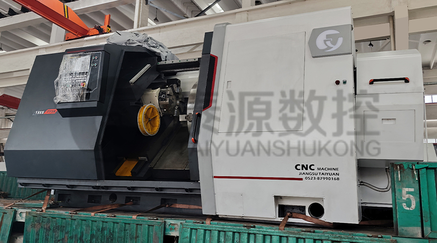
Φ1000mm Oil Pipe Processing Lathe Machine
While often used interchangeably, vibration and chatter represent distinct phenomena with different causes and solutions. Proper diagnosis is essential for implementing effective corrective measures in your pipe threading operations.
A stable machine foundation forms the first line of defense against vibration problems. Many chatter issues in CNC threading lathes can be traced back to inadequate installation or leveling.
Even slight misleveling creates internal stresses in machine structures that amplify vibration during cutting operations. Proper installation is critical for vibration-free performance.
The mass and composition of your machine foundation significantly influence vibration damping capabilities. These specifications help prevent vibration in pipe threading across various machine configurations.
| Machine Weight | Minimum Foundation Depth | Reinforcement Requirement | Isolation Recommendation |
| Under 3,000 kg | 300 mm | Standard rebar grid | Optional isolation pads |
| 3,000-8,000 kg | 500 mm | Heavy rebar with edge beams | Recommended for all installations |
| 8,000-15,000 kg | 800 mm | Reinforced concrete with vibration damping | Essential for precision work |
| Over 15,000 kg | 1,200 mm | Engineered foundation with damping additives | Custom isolation system required |
Inadequate workpiece support represents the most frequent cause of chatter in long pipe threading applications. Implementing proper support strategies is essential for achieving chatter-free threading results.
Properly positioned steady rests counteract the deflection forces that initiate chatter in long, slender workpieces. Strategic placement maximizes damping effectiveness.
Chuck jaw configuration directly influences workpiece stability and vibration transmission. Selecting the appropriate jaw type for your specific material prevents threading vibration solutions from being compromised at the fundamental holding stage.
| Pipe Material | Recommended Jaw Type | Gripping Pressure | Special Considerations |
| Carbon Steel | Hard serrated jaws | Medium-High | Standard configuration for most applications |
| Stainless Steel | Fine serration carbide-tipped | Medium | Prevent work hardening with excessive pressure |
| Alloy Steel | Heat-treated grip jaws | High | Ensure sufficient torque capacity for heavy cuts |
| Non-Ferrous | Soft aluminum or copper jaws | Low-Medium | Prevent surface damage while maintaining grip |
| Thin-Wall Tubing | Collet chuck or expanding mandrel | Low | Distribute gripping force to prevent deformation |
Tooling represents the contact point where vibration initiates and amplifies. Strategic selection of tool holders and inserts can dramatically improve threading machine stability and chatter resistance.
Tool holder selection significantly impacts vibration performance through their mass, overhang, and interface stiffness. These factors collectively determine the system's natural frequency.
Modern threading inserts incorporate specific geometric features designed to combat chatter through variable pitch designs and specialized edge preparations. Understanding these features helps select optimal CNC lathe threading tools for vibration-prone applications.
Even with perfect setup and tooling, inappropriate cutting parameters can generate destructive vibration. These proven strategies help identify stable cutting windows for vibration-free pipe machining across various materials.
The relationship between cutting speed, feed rate, and depth of cut creates complex dynamic interactions that either promote or suppress vibration. Mastering these relationships is key to stable threading.
Modern machining theory identifies specific spindle speed ranges where cutting becomes naturally stable due to phase relationships in the vibration cycle. Applying stability lobe principles can dramatically improve threading process optimization in production environments.
| Material Type | Typical Stable Speed Range | Depth of Cut Limit | Feed Reduction Factor |
| Mild Steel | 180-250 SFM | 0.5-0.8mm | 0% (standard parameters) |
| Stainless 304 | 120-180 SFM | 0.3-0.6mm | 15-20% reduction from steel |
| Alloy Steel | 150-220 SFM | 0.4-0.7mm | 10% reduction from mild steel |
| Aluminum | 500-800 SFM | 0.8-1.2mm | 20-30% increase possible |
| Titanium | 60-100 SFM | 0.2-0.4mm | 25-35% reduction necessary |
For particularly challenging applications, specialized damping technologies can suppress vibration where conventional methods reach their limits. These advanced solutions represent the cutting edge of CNC pipe threading lathe technology.
Modern damping systems detect and counteract vibration in real-time using various physical principles. Understanding their operation helps select appropriate technology for specific vibration problems.
Regular maintenance prevents the gradual degradation that leads to vibration problems. These specific procedures target the systems most critical to maintaining stable pipe threading operations over the long term.
This specialized maintenance schedule focuses specifically on preventing vibration issues in precision threading applications, complementing standard machine maintenance protocols.
The most frequent cause of chatter in CNC pipe threading lathe applications is insufficient workpiece support, particularly when threading long pipes. As the cutting tool engages the workpiece, it generates deflection forces that cause the pipe to bend slightly away from the cut. This deflection creates a variable depth of cut that initiates a self-exciting vibration cycle. Proper implementation of steady rests, correct chucking pressure, and optimal cutting parameters collectively address this fundamental challenge. Machines from experienced manufacturers like Jiangsu Taiyuan CNC Machine Tool Co., Ltd. often incorporate enhanced rigidity specifically designed to mitigate these common chatter sources.
Tool overhang dramatically impacts vibration by reducing the natural frequency of the cutting system. Every doubling of overhang decreases rigidity by approximately 8 times, making the system more susceptible to chatter at lower cutting forces. For optimal threading vibration solutions, maintain the shortest possible tool overhang that clears the workpiece and chuck. As a general rule, the overhang should not exceed 4 times the tool holder height for roughing operations or 3 times for finishing. Using modular tooling systems with minimal component interfaces further enhances stability in demanding pipe threading operations.
Absolutely. Cutting fluid contributes to vibration reduction through multiple mechanisms. Proper coolant application lowers cutting temperatures, reducing thermal expansion that can alter cutting geometry during operation. High-pressure through-tool coolant effectively breaks chips, preventing long, stringy chips from wrapping around the workpiece and creating unbalanced forces. Additionally, some advanced cutting fluids contain extreme pressure additives that reduce cutting forces by improving lubrication at the tool-workpiece interface. For the best vibration-free pipe machining results, ensure coolant is directed precisely at the cutting edge with sufficient pressure and volume to penetrate the cutting zone completely.
Several specific maintenance procedures directly impact vibration performance in CNC threading lathes. Regularly check spindle bearing preload using dial indicators to detect developing play. Verify ball screw preload by measuring positional consistency during direction changes. Inspect way surfaces for wear patterns that indicate alignment issues. Check for loose fasteners in the tool turret and tailstock assembly. Monitor drive belt tension and condition, as slipping belts create irregular motion that initiates vibration. Quality machines from established manufacturers like Jiangsu Taiyuan CNC Machine Tool Co., Ltd. typically feature enhanced maintenance accessibility specifically designed to facilitate these critical vibration-prevention checks.
Distinguishing between machine-generated and process-induced vibration requires systematic troubleshooting. Run the machine at operating speeds without cutting - if vibration persists, it's likely machine-related from sources like imbalanced rotating components, bearing issues, or drive system problems. If vibration only occurs during cutting, it's process-induced chatter. For machine vibration, frequency analysis can identify the source: spindle frequency vibrations indicate imbalance, while gear mesh frequencies point to transmission issues. Process chatter typically shows variable frequencies that change with cutting parameters. Modern CNC pipe threading lathe systems often include built-in vibration analysis capabilities to assist with this diagnostic process.
Related Products
 Model:TYSK-630T Drill Pipe, Joint & Coupling Lathe
The machine adopts a FANUC CNC system with stable processing accuracy and flexible programming functions to ensure that the processed parts meet strict industry standards. The high torque and heavy-load design can cope with long-term continuous work and has strong durability.
 Model:TYSK-1355 Oil Pipe Processing Lathe
The machine adopts a FANUC CNC system with stable processing accuracy and flexible programming functions to ensure that the processed parts meet strict industry standards. The high torque and heavy-load design can cope with long-term continuous work and has strong durability.
 Series:TYSK-NKJ Screw-on machine/Casing and tubing coupling bucking unit
The machine uses a hydraulic motor, mechanical floating mechanism, and real-time torque detection, adapts to material bending, and prevents material deformation. Auxiliary machines are configured to help with semi-automation.
 Long, heavy material solutions Automatic loading and unloading mechanism for pipe threading
The special flexible support mode can effectively reduce the influence of workpiece bending on processing and improve the yield. Strictly matching with our pipe threading lathe.
 Modular Iron Chip Crusher High strength crusher for chip
The blades are made of high-strength materials and reasonably placed at the exit of the chip extractor to break the clump iron chips.Reduce the risk of rollback and improve waste frame utilization.
 Series:TYSK-HB Semi-automatic wear-resistant band welder
Applicable to ARNCO 100XT, 200XT, 300XT. Support φ1.2-2.0 cored or solid wire surfacing welding.Can be equipped with single gun spray welding and double gun spray welding two ways. Support PLC or CNC system control.
 Model:TYSK-XQJ-550 Medium & Large PTFE Film Skiving Machine
Designed to process blanks with a maximum diameter of 550 mm and a maximum length of 1000 mm. We can also customize according to the needs of users. Friendly change speed and thickness with CNC.
