



 English
 عربى
 中文简体

Reminder information


Nov 11, 2026
Content
CNC milling machines make screw pump rotors by generating a helical profile through coordinated rotary and linear motion. In oilfield progressing cavity pumps, the rotor turns inside an elastomer stator, so the process must hold lobe form, lead, runout, surface finish, and coating allowance along a workpiece that may be long and slender. The machine, workholding, CAM strategy, cutter access, and inspection plan matter more than the nominal number of axes.
On a screw pump rotor, the cutting program cannot treat the flute as a repeated groove. The flank is a continuous helical surface, and the lead must remain consistent over the active length. A change in tool axis, a small CAM tolerance error, or deflection in a long workpiece can show up as a tight spot against the stator, uneven sealing, or localized wear. Milling therefore works from a 3D rotor model, not from a simple 2D section.
The rotor also carries practical references beyond the helical form: journals, drive features, end faces, and often a coating allowance. Each transition between turned, milled, and coated surfaces needs a clear datum strategy. If the milling setup loses the centerline, the finished rotor may pass a profile check and still run out in the pump assembly.
Definition: A screw pump rotor is the helical steel member that rotates inside an elastomer stator in a progressing cavity pump. Its profile, lead, and surface condition create the sealed cavities that move fluid; the stator usually has one more lobe than the rotor.
The route usually starts with a cut blank and turned datums. Turning establishes the centerline, end faces, and journals that the milling setup will use. The helical flutes are then roughed, semi-finished, and finished, with a stress-relief step added only when the material and drawing require it. A final coating may follow, so the milling operation must leave the correct coating allowance.
| Stage | Purpose | What to verify |
|---|---|---|
| Blank and datums | Establish centerline and stable clamping references | Straightness, center holes, journal runout, material certificate |
| Rough milling | Remove bulk stock without loading the slender part | Cutter engagement, chip evacuation, steady-rest pressure, allowance |
| Stress relief | Reduce movement before finishing where specified | Process record and dimensional check before semi-finishing |
| Semi-finish and finish | Generate flank, root, and lead to drawing | Toolpath verification, cutter wear, surface finish, lead and profile checks |
| Coating and final inspection | Apply wear or corrosion protection and verify final geometry | Coating thickness, post-coating profile, runout, balance if required |
The sequence is not fixed. A short, stiff rotor may go from roughing to finishing with minimal intermediate handling. A long rotor may need additional steady-rest positions, re-datuming, or a separate finishing pass after stress relief. The drawing, material condition, and required surface finish should decide the route, not a standard template.
Long rotors need support that does not fight the toolpath. A between-centers setup with a headstock drive, tailstock, and one or more steady rests is common. The steady rest must contact a prepared journal, not a raw or finished helical surface, and its pressure has to be repeatable. If the part deflects during roughing, the finishing pass will cut an inconsistent stock allowance and may not clean up the flank.
Two common CNC milling approaches are end-mill interpolation on a 4- or 5-axis machining center and whirlwind milling with a rotating cutter head. End-mill interpolation is flexible for prototypes and mixed work; simultaneous 5-axis motion can keep the cutter oriented on the flank and root. Whirlwind milling can remove material quickly on dedicated rotor work, but the setup and cutter geometry are more specific. The choice should follow rotor length, lot size, profile tolerance, and the shop's inspection capability.
Useful when the rotor can be rotated while the cutter follows the lead. It can be simpler to program, but the fixed tool attitude may limit access to steep flanks and may leave marks that need a finishing pass.
Allows the cutter to tilt along the helical path. That can improve flank access and reduce rubbing, but it also raises the demand on machine kinematics, postprocessing, simulation, and collision checking.
Illustrative Example: A hypothetical shop has a long 4140 rotor with a hard-chrome finish allowance. A 4-axis setup might rough the helical channel, but the finishing pass still needs enough tool-axis freedom to reach the flank without rubbing the shank. If the machine cannot tilt the cutter, the shop may need a different cutter shape, a whirlwind head, or a revised process route. The example does not show that one setup is always better; it shows why the setup must be checked against part length, flank access, and coating allowance.
Oilfield service adds wear and corrosion to the geometry problem. Produced fluids may carry sand, scale, or gas, and the rotor may be specified in a material and coating selected for the well conditions. A rotor that measures correctly but has a poor surface finish, embedded grit from a dirty setup, or an uneven coating can wear the stator faster. Machining and coating should be treated as one chain, not separate operations. The machining plan should reflect that wear path, as discussed in this overview of CNC machining in oilfield equipment production.
Material selection may include 4140 or 42CrMo steel with hard chrome, 17-4PH stainless, or duplex grades for more corrosive service. If sour service is specified, NACE MR0175/ISO 15156 may govern material qualification and hardness limits; that standard does not replace the rotor drawing or the buyer's inspection plan. For progressing cavity pump systems, ISO 15136-1 provides a system-level reference, but the machining acceptance criteria still come from the rotor design and the agreed inspection document.
Buyers should not approve a rotor process from a machine list alone. The approval should connect the rotor drawing, CAM model, setup, cutting tools, coating allowance, and inspection method. A supplier that can explain those links is easier to audit than one that quotes only an axis count or a spindle speed.
These questions are not administrative. They decide whether the helical form that leaves the machine is the same form that reaches the stator.
CNC milling is a workable way to produce screw pump rotors for oilfield applications when the process is built around the helical geometry, not around a generic milling routine. The machine must provide stable support and enough controlled tool motion; the CAM strategy must reach the flank without rubbing; and the inspection plan must prove lead, profile, runout, finish, and coating allowance. For buyers, the useful question is not simply how many axes the machine has, but whether the supplier can show how each step protects the rotor's fit against the stator.
Related Products
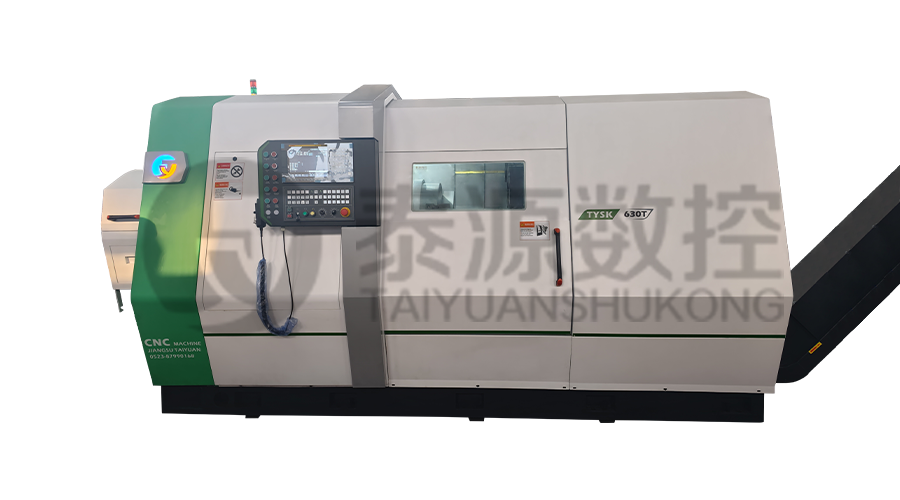 Model:TYSK-630T Drill Pipe, Joint & Coupling Lathe
The machine adopts a FANUC CNC system with stable processing accuracy and flexible programming functions to ensure that the processed parts meet strict industry standards. The high torque and heavy-load design can cope with long-term continuous work and has strong durability.
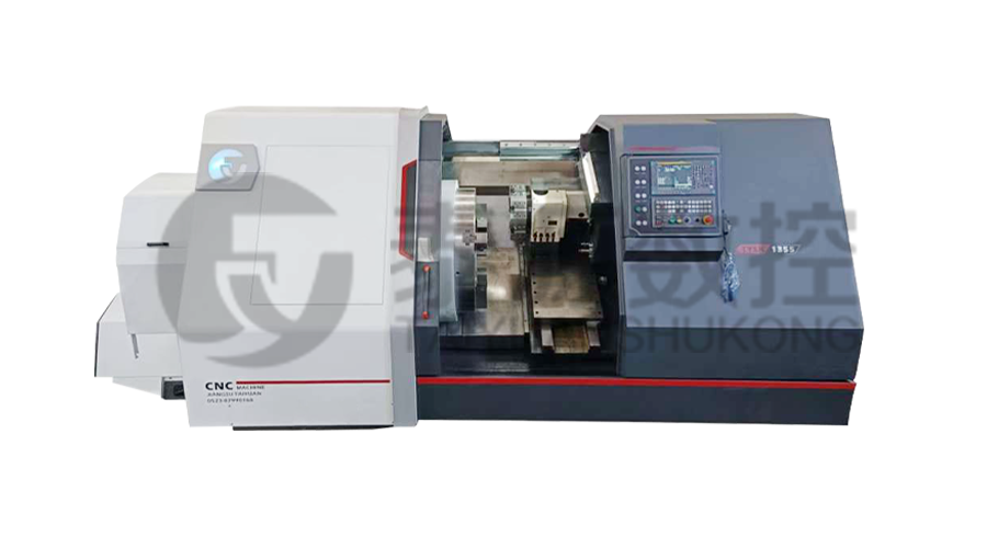 Model:TYSK-1355 Oil Pipe Processing Lathe
The machine adopts a FANUC CNC system with stable processing accuracy and flexible programming functions to ensure that the processed parts meet strict industry standards. The high torque and heavy-load design can cope with long-term continuous work and has strong durability.
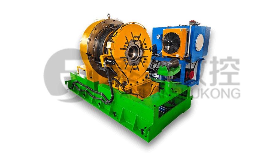 Series:TYSK-NKJ Screw-on machine/Casing and tubing coupling bucking unit
The machine uses a hydraulic motor, mechanical floating mechanism, and real-time torque detection, adapts to material bending, and prevents material deformation. Auxiliary machines are configured to help with semi-automation.
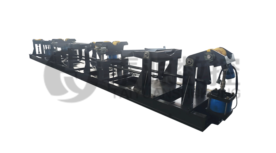 Long, heavy material solutions Automatic loading and unloading mechanism for pipe threading
The special flexible support mode can effectively reduce the influence of workpiece bending on processing and improve the yield. Strictly matching with our pipe threading lathe.
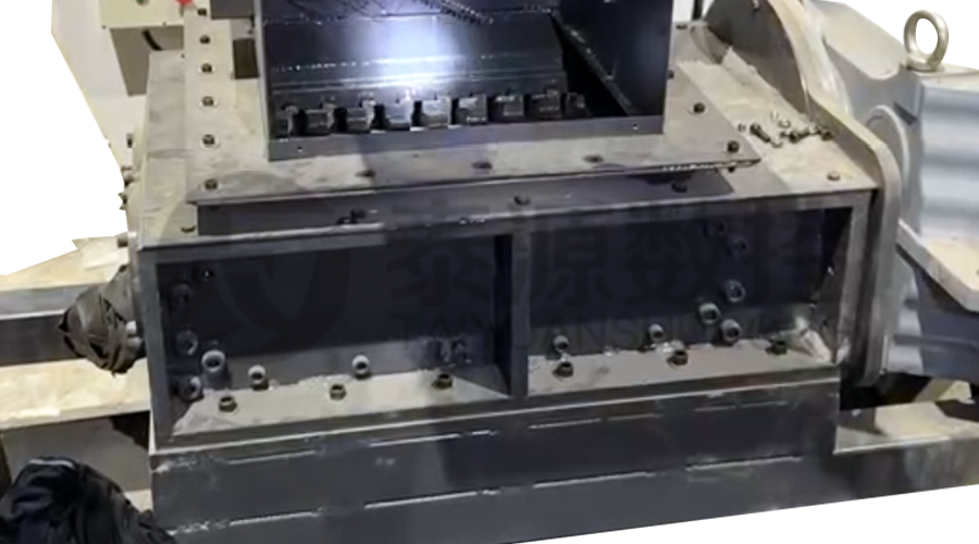 Modular Iron Chip Crusher High strength crusher for chip
The blades are made of high-strength materials and reasonably placed at the exit of the chip extractor to break the clump iron chips.Reduce the risk of rollback and improve waste frame utilization.
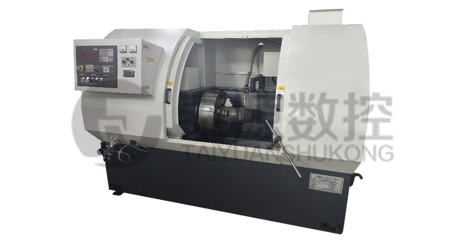 Series:TYSK-HB Semi-automatic wear-resistant band welder
Applicable to ARNCO 100XT, 200XT, 300XT. Support φ1.2-2.0 cored or solid wire surfacing welding.Can be equipped with single gun spray welding and double gun spray welding two ways. Support PLC or CNC system control.
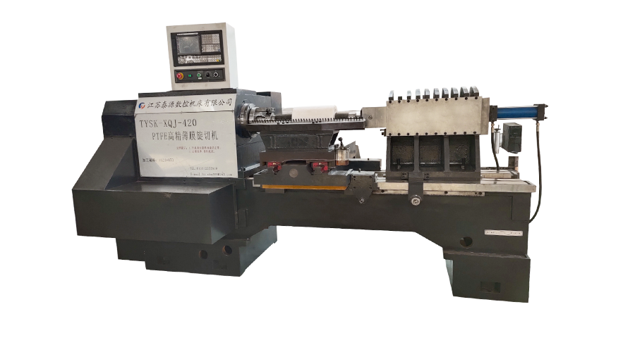 Model:TYSK-XQJ-550 Medium & Large PTFE Film Skiving Machine
Designed to process blanks with a maximum diameter of 550 mm and a maximum length of 1000 mm. We can also customize according to the needs of users. Friendly change speed and thickness with CNC.
