



 English
  عربى
عربى  中文简体
中文简体

Reminder information

Oct 09, 2026
Content
A shop orders a CNC pipe threading lathe rated for 5-1/2 in. casing, then wins a contract that includes coupled joints. The pipe body measures 139.7 mm across and slides through the spindle without complaint. The coupling measures roughly 154 mm across and will not clear the cross slide once the chuck jaws are fitted. Nothing is broken. The machine was selected against the pipe and never checked against the coupling.
Four figures decide whether a machine fits a given pipe and coupling schedule: the largest coupling outside diameter the machine can swing, the spindle bore, the bed length and steady rest arrangement, and the thread form plus make-up torque the machine can produce. Pipe body diameter alone tells you almost nothing, because couplings, tool joints and hardbanding all sit further out than the pipe they connect.
Sales sheets lead with maximum pipe diameter. The useful question is narrower: does every item in your schedule fit inside the machine envelope at the same time? A lathe can swing a 300 mm coupling and still fail on a 9 m pipe if the steady rests are spaced for joint-length work only.
| Check | What it must cover | Rule of thumb | Typical failure if missed |
|---|---|---|---|
| Swing over cross slide | Largest coupling or tool joint OD, plus jaw and tool clearance | Coupling OD + about 20 mm | Coupling rubs the cross slide or jaws; light cuts only |
| Spindle bore | Pipe or coupling that must pass through the headstock | Maximum OD + 10-15 mm for pass-through work | Pipe cannot be fed through; short chuck work only |
| Bed length and steady rests | Longest pipe length range in the schedule | Support roughly every 2-3 m of pipe | Sag, chatter and taper drift in the thread |
| Thread form, pitch and taper | 8-round at 8 TPI, buttress at 5 TPI, 1:16 taper, premium forms | Electronic thread cycle with taper and pitch compensation | Gauge rejection on pitch diameter |
| Make-up torque (bucking) | Smallest and largest coupling in the schedule | Useful control accuracy at the low end of the torque band | Under-torqued joints or yielded couplings |
Read the table as a chain. Each row can veto the purchase on its own, and a comfortable margin in three rows does not compensate for a shortfall in the fourth.
Coupling bodies are always larger than the pipe they connect, and the difference is not small. Three reference sizes: 2-7/8 in. tubing runs 73.0 mm at the pipe body against an 88.9 mm coupling; 5-1/2 in. casing runs 139.7 mm against 153.7 mm; 9-5/8 in. casing runs 244.5 mm against 269.9 mm. A machine sized on pipe diameter alone can miss the coupling by 15 to 25 mm, which is exactly the range where a good lathe turns into an unsuitable one.
Drill pipe adds a second complication. Tool joints are up-sized by design, and hardbanding applied to the joint adds still more material to the outside diameter. If the schedule contains hardbanded drill pipe, size the swing on the banded joint, not on the bare tool joint. The same logic applies to wear-resistant casing couplings and to any connection with a special-clearance or oversized coupling.
A practical clearance rule: allow the largest coupling outside diameter plus about 20 mm when checking swing over the cross slide. That margin covers chuck jaw height, tool approach and the small eccentricity you get when a pipe is not perfectly straight.
There are two ways to hold an oilfield pipe on a lathe, and they place different demands on the spindle. In pass-through work the pipe is fed through the headstock and supported by steady rests, so the bore must clear the pipe outside diameter with room for the chuck and for a slightly bent tube. In chuck work the pipe is gripped close to the end and only a short length enters the spindle, so swing and steady rest capacity set the limit and the bore is almost irrelevant.
That distinction changes the answer to "what bore do I need". A 5-1/2 in. casing pipe at 139.7 mm is tight in a 160 mm bore and comfortable in a 200 mm bore. Large bores also carry a cost: bigger spindle bearings, heavier chucks, lower maximum spindle speed. On long, thin-walled pipe that lower speed is often a benefit rather than a limitation, because pipe whips and chatters when it is spun fast.
The interaction between bore size, chuck type and the way pipe is supported is covered in more detail in this note on spindle bore requirements for pipe threading machines.
API casing and tubing lengths come in ranges: roughly 4.9 to 7.6 m, 8.5 to 9.8 m, and 11.6 to 12.2 m. A lathe that handles the first range comfortably may need extra steady rests and a longer bed for the third. Support spacing matters more than total bed length, because an unsupported span of pipe sags under its own weight and cuts a taper into the thread.
Weight compounds the problem. A 9-5/8 in., 47 lb/ft casing joint weighs about 70 kg per metre, so a 12 m joint is close to 840 kg before the coupling is fitted. Moving that mass between steady rests without marking the surface is a handling question as much as a machining question, and it is one of the main reasons integrated loading and unloading mechanisms pay for themselves once pipe passes about 6 m.
Some shops never machine a full pipe length. They cut threads on tool joints, re-cut coupling threads or machine coupling blanks, and for that work a short, stiff lathe with a large chuck and a big bore is more productive than a long bed machine. Long beds invite deflection on short work and consume floor space. Full-length pipe threading and joint-only work are different purchases, even though both arrive as CNC lathes.
Two thread families dominate oilfield tubular work. The 8-round form runs at 8 threads per inch; the buttress form runs at 5 threads per inch. Both are cut on a 1:16 taper, which works out at 62.5 mm of diameter change per metre of axial travel. Pitch and taper hold at the same time only when the machine synchronizes spindle rotation and Z-axis feed electronically. A mechanical leadscrew lathe cannot compensate for the taper while holding pitch, and it will not repeat closely enough on pitch diameter for API work.
Pitch diameter, not thread crest, is what a ring gauge inspects. API 5B defines the gauging practice and the tolerance band, which is a small fraction of a millimetre. A machine that turns good-looking threads can still fail a gauge check if the threading cycle has no pitch error compensation, if the tool holder deflects under load, or if spindle encoder resolution is coarse.
Premium connections change the picture again: proprietary forms, tighter tolerances, and often a requirement to record torque-turn curves for every joint. Before committing, confirm which forms the control generates as standard cycles and which need a custom macro.
A screw-on machine holds the pipe in one chuck and the coupling in another, then rotates one against the other to a specified make-up torque. Torque has to be right at both ends of the size range. Too little and the joint can back off or leak in service; too much and the coupling yields, the threads gall, or the seal face is damaged.
A machine specified for large casing has a lot of torque headroom, and that headroom becomes a problem when the same machine must make up small tubing couplings, where the target torque is a small fraction of the maximum. Check the torque curve at the low end rather than only the peak, and ask for control accuracy across the whole band. Changeover time between sizes matters just as much: a machine that takes hours to reset for a different coupling size quietly destroys the economics of a mixed order book.
Matching CNC machining equipment to oilfield pipe and coupling sizes is an envelope exercise, not a specification comparison. Write down every pipe size, coupling diameter, thread form and torque value; convert them into a maximum outside diameter, a bore requirement, a support plan, a thread capability and a torque range; then check each one against the machine. Where one of those five fails, the machine fails, no matter how good the brochure looks.
If the schedule is mixed or still growing, it pays to compare the envelope against our CNC pipe threading machines before the purchase order is raised, using actual coupling diameters and torque values rather than nominal pipe sizes.
Related Products
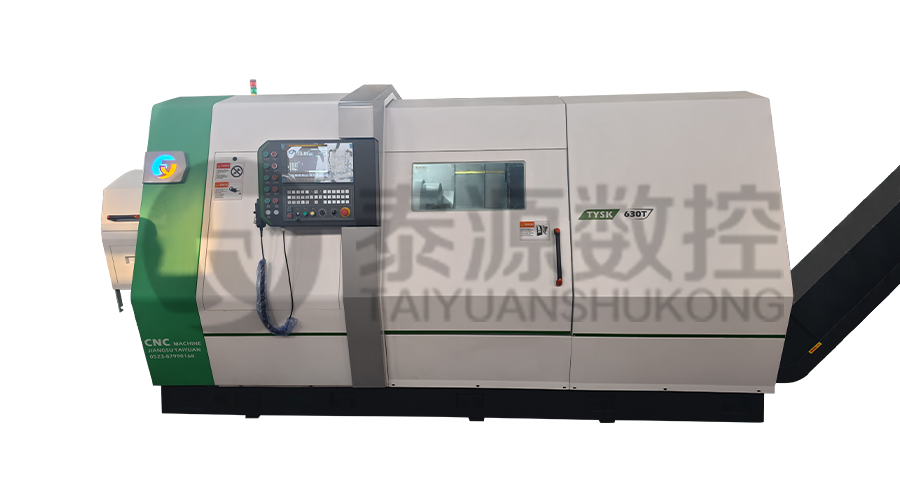 Model:TYSK-630T Drill Pipe, Joint & Coupling Lathe
The machine adopts a FANUC CNC system with stable processing accuracy and flexible programming functions to ensure that the processed parts meet strict industry standards. The high torque and heavy-load design can cope with long-term continuous work and has strong durability.
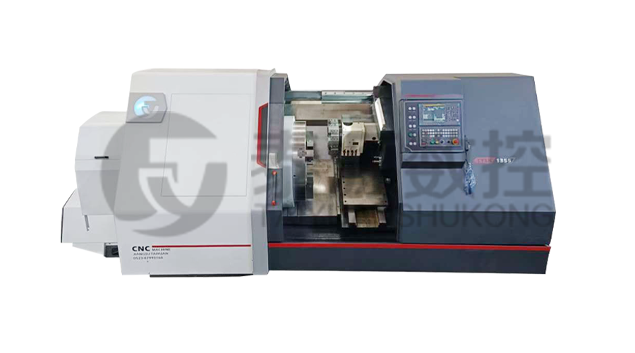 Model:TYSK-1355 Oil Pipe Processing Lathe
The machine adopts a FANUC CNC system with stable processing accuracy and flexible programming functions to ensure that the processed parts meet strict industry standards. The high torque and heavy-load design can cope with long-term continuous work and has strong durability.
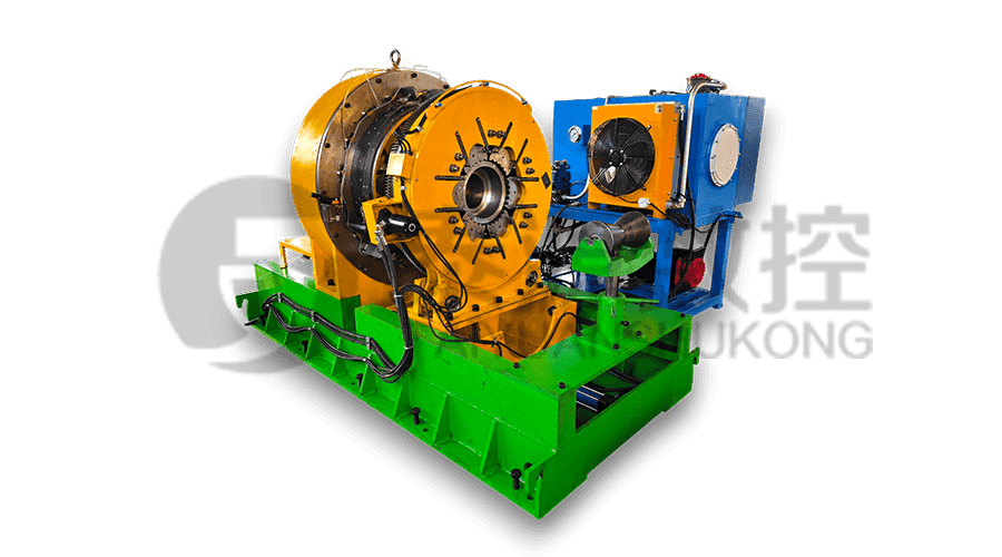 Series:TYSK-NKJ Screw-on machine/Casing and tubing coupling bucking unit
The machine uses a hydraulic motor, mechanical floating mechanism, and real-time torque detection, adapts to material bending, and prevents material deformation. Auxiliary machines are configured to help with semi-automation.
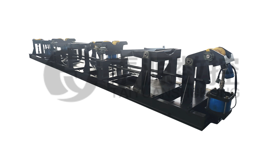 Long, heavy material solutions Automatic loading and unloading mechanism for pipe threading
The special flexible support mode can effectively reduce the influence of workpiece bending on processing and improve the yield. Strictly matching with our pipe threading lathe.
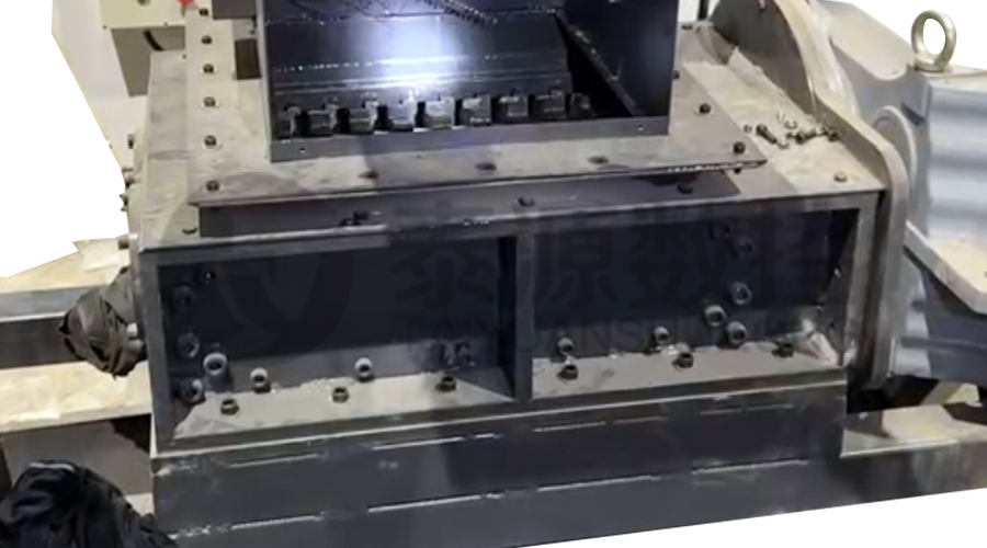 Modular Iron Chip Crusher High strength crusher for chip
The blades are made of high-strength materials and reasonably placed at the exit of the chip extractor to break the clump iron chips.Reduce the risk of rollback and improve waste frame utilization.
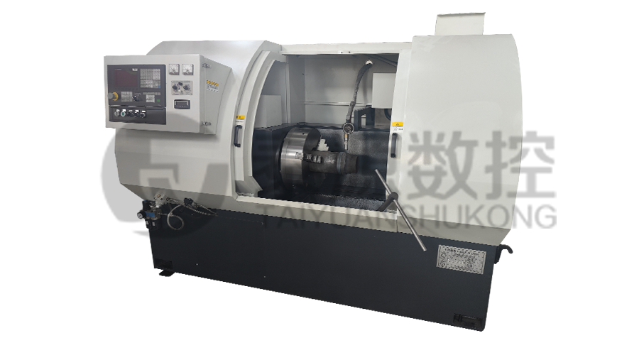 Series:TYSK-HB Semi-automatic wear-resistant band welder
Applicable to ARNCO 100XT, 200XT, 300XT. Support φ1.2-2.0 cored or solid wire surfacing welding.Can be equipped with single gun spray welding and double gun spray welding two ways. Support PLC or CNC system control.
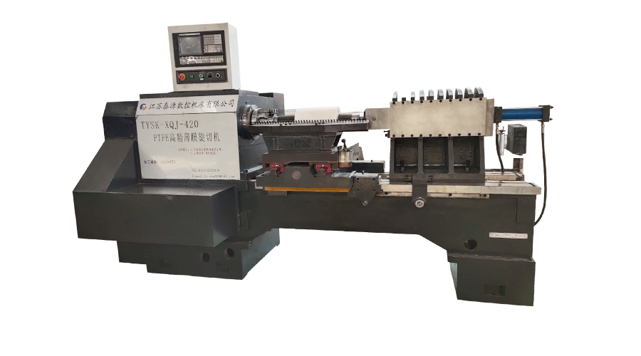 Model:TYSK-XQJ-550 Medium & Large PTFE Film Skiving Machine
Designed to process blanks with a maximum diameter of 550 mm and a maximum length of 1000 mm. We can also customize according to the needs of users. Friendly change speed and thickness with CNC.
