



 English
  عربى
عربى  中文简体
中文简体

Reminder information

Oct 07, 2026
Content
A shop that buys a threading lathe sized for 2 3/8-inch tubing usually finds out it was the wrong machine on the day a casing order arrives. The spindle bore will not pass the pipe, the chuck cannot hold the weight, and the thread gauges start telling a different story on the second shift. The decision that matters is not which control brand sits on the panel. It is the pipe envelope, the thread form, the rigidity of the cutting structure, and the make-up torque the coupling has to survive.
Work through the requirements in that order and the machine choice becomes fairly narrow. Skip a step and the gap shows up later as scrap threads, rejected couplings, or a lathe that sits idle because it can only run half the product mix.
Every number on a lathe quotation is downstream of the pipe you intend to machine. Write down four figures first: outside diameter range, maximum wall thickness, joint length, and single-joint weight. For oilfield tubulars the length follows the API range, with Range 1 joints around 6.1 m, Range 2 around 9.4 m and Range 3 around 13.7 m, and the bed, steady rest positions and tailstock travel all have to suit the range you actually buy.
The spindle bore is the first hard limit. Pipe threading lathes normally pass the pipe through the spindle so both ends can be machined without re-chucking, which means the through-bore must exceed the largest pipe body you will ever run. A 165 mm bore covers most tubing and small-to-medium casing work; large-diameter casing pushes the requirement into the 250–350 mm class and the machine mass grows with it. If the bore is marginal, the operator ends up machining with the pipe hanging out of the chuck, and the thread taper suffers.
For a closer look at bore sizing and its effect on workholding, see these notes on spindle bore requirements for pipe threading machines.
| Pipe OD range | Typical product | Through-bore class | Chuck and support | Practical note |
|---|---|---|---|---|
| 1.660–2 3/8 in | Tubing, small couplings | 80–110 mm | 3-jaw power chuck, 250 mm | Higher spindle speed, light cuts |
| 2 7/8–4 1/2 in | Tubing and casing | 130–170 mm | 3-jaw chuck, 315–400 mm | The most common shop class |
| 5 1/2–7 in | Casing | 200–240 mm | 4-jaw independent, 500 mm | Steady rest strongly recommended |
| 9 5/8–13 3/8 in | Large casing and couplings | 350 mm and above | 4-jaw chuck, 800 mm and above | Heavy bed, low speed, high torque |
Oilfield threads are not generic machine threads. Casing and tubing connections are defined by API 5B, which fixes the thread form, taper and dimensional tolerances that a ring or plug gauge will check. The common casing thread is an 8-thread-per-inch buttress form cut on a 1:16 taper, and acceptance covers pitch diameter, thread height, lead variation and taper. A lathe that cannot hold those tolerances consistently produces joints that fail gauging, and that is a scrap cost rather than a rework cost.
Two machine features carry most of this burden. The first is the control's threading capability: single-point threading with accurate spindle encoding, thread repair and re-chasing, and enough servo response to hold lead across the full thread length. The second is thermal stability. A lathe that grows 20 microns between a cold start and a warm afternoon will drift out of pitch diameter tolerance, so spindle cooling, bed design and a warm-up routine matter more here than on a general turning lathe.
Gauging should be planned alongside the machine, not after it. Budget for the ring and plug gauges that match your connection types, and write into the purchase contract that acceptance will be judged with those gauges on your own pipe, not on a polished test bar. Compliance details for coupling and bucking work are covered in this reference on API 5CT casing and tubing coupling bucking lathe compliance.
Advertised swing is not working capacity. On P110 and Q125 grades the cutting forces at a 1:16 taper are considerable, and the material work-hardens at the surface. The machine has to absorb that force without deflecting the workpiece, because a few microns of movement between tool and thread flank shows up directly as lead error.
Look at structural facts rather than marketing numbers: bed width and guideway hardness, spindle bearing arrangement and preload, the section of the tailstock quill, and whether the steady rest clamps on a machined surface or on the raw pipe OD. Heavier machines tolerate deeper passes and longer tool life; lighter machines force the operator into multiple spring passes, which is slow and inconsistent. Chatter is the visible symptom of a machine at its limit, and no control setting will fix a structure that is too light for the cut.
Drill pipe tool joints are short, thick and much harder than casing. They call for a different geometry: a larger chuck, a shorter effective bed, and a spindle that delivers torque at low speed rather than top-end rpm. If drill pipe joints are part of your mix, treat them as a separate requirement when you size the lathe instead of assuming the casing machine will cover them.
Cutting the pin thread and making up the coupling are two separate operations, and they are often confused during machine selection. A threading lathe cuts the thread. A bucking unit, or screw-on machine, holds the pipe and rotates the coupling to a controlled make-up torque so the shoulder seats properly and the connection can withstand downhole loads.
Torque requirement scales with diameter and wall thickness. A small tubing connection may make up in the low hundreds of foot-pounds, while large casing connections run into several thousand. The bucking machine therefore needs a torque specification, a measurement method, and a recording system that produces a trace for each joint. If your customer asks for make-up records, and most operators do, the machine has to log them.
Ask one question before choosing between the two machine types: is the coupling supplied loose and torqued on site, or is it bucked on at the mill or pipe yard? The answer decides whether you need a threading lathe, a bucking unit, or both.
Manual loading of a 9-metre, 500 kg joint is slow and physically punishing, and it is the main reason a shop with a good lathe still misses its output target. Automatic loading and unloading mechanisms change the arithmetic. They cut non-cutting time per joint, keep the operator away from the rotating pipe, and make unattended shifts realistic for repetitive sizes.
Cycle time is not spindle speed multiplied by thread length. Count the whole sequence: load, clamp, face, chamfer, thread, gauge, unload, and the walking between stations. On a typical casing joint the threading cut may take two to three minutes, while handling and gauging take longer than that. That is where automation pays back.
Automation should be specified with the lathe, not added afterwards. The interface between loader, chuck, steady rest and control has to be designed as one system; retrofitting later costs more and usually compromises the layout.
Acceptance is where the specification becomes enforceable. Build the run-off test around your own pipe, your own thread form and your own gauges, and agree the pass criteria in writing before the machine ships.
The right CNC pipe threading lathe is the one that covers your real product mix with margin on bore, torque and rigidity, not the one with the largest advertised swing. Oversizing costs capital and floor space; undersizing costs scrap, rework and lost orders. Between those two, undersizing is the more expensive mistake, because a rejected thread cannot be recovered and a missed delivery is rarely forgiven.
Write the requirement list in the order this article follows: pipe envelope, thread form and gauging, cutting structure, make-up torque, then automation and acceptance. Take that list to a machine builder and ask for a run-off on your pipe. The machine that passes that test on your material is the correct answer, regardless of what the brochure says.
Related Products
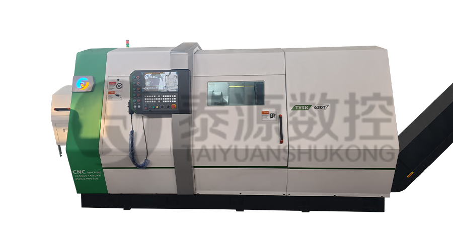
Model:TYSK-630T Drill Pipe, Joint & Coupling Lathe
The machine adopts a FANUC CNC system with stable processing accuracy and flexible programming functions to ensure that the processed parts meet strict industry standards. The high torque and heavy-load design can cope with long-term continuous work and has strong durability.
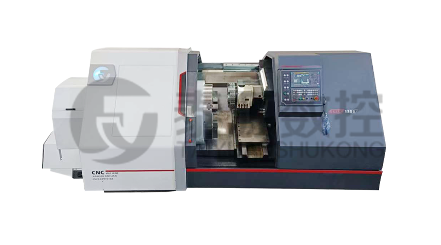 Model:TYSK-1355 Oil Pipe Processing Lathe
The machine adopts a FANUC CNC system with stable processing accuracy and flexible programming functions to ensure that the processed parts meet strict industry standards. The high torque and heavy-load design can cope with long-term continuous work and has strong durability.
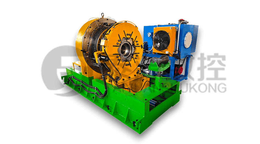 Series:TYSK-NKJ Screw-on machine/Casing and tubing coupling bucking unit
The machine uses a hydraulic motor, mechanical floating mechanism, and real-time torque detection, adapts to material bending, and prevents material deformation. Auxiliary machines are configured to help with semi-automation.
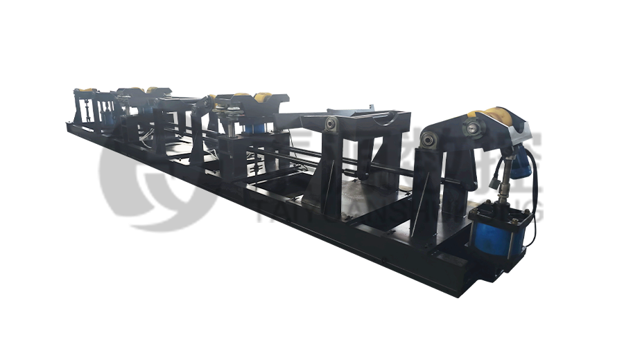 Long, heavy material solutions Automatic loading and unloading mechanism for pipe threading
The special flexible support mode can effectively reduce the influence of workpiece bending on processing and improve the yield. Strictly matching with our pipe threading lathe.
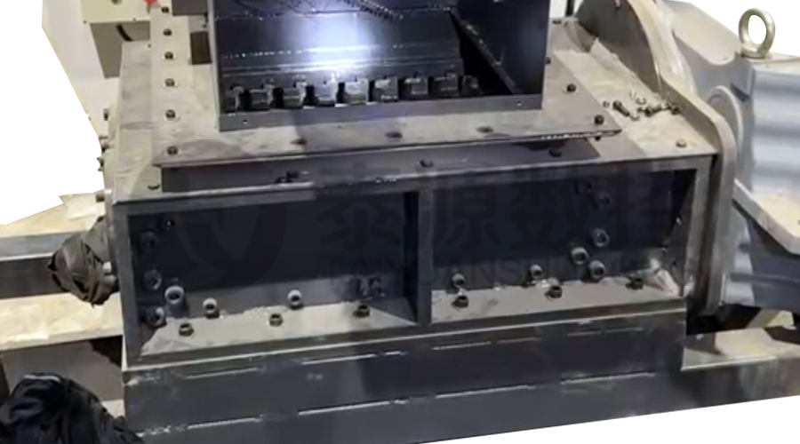 Modular Iron Chip Crusher High strength crusher for chip
The blades are made of high-strength materials and reasonably placed at the exit of the chip extractor to break the clump iron chips.Reduce the risk of rollback and improve waste frame utilization.
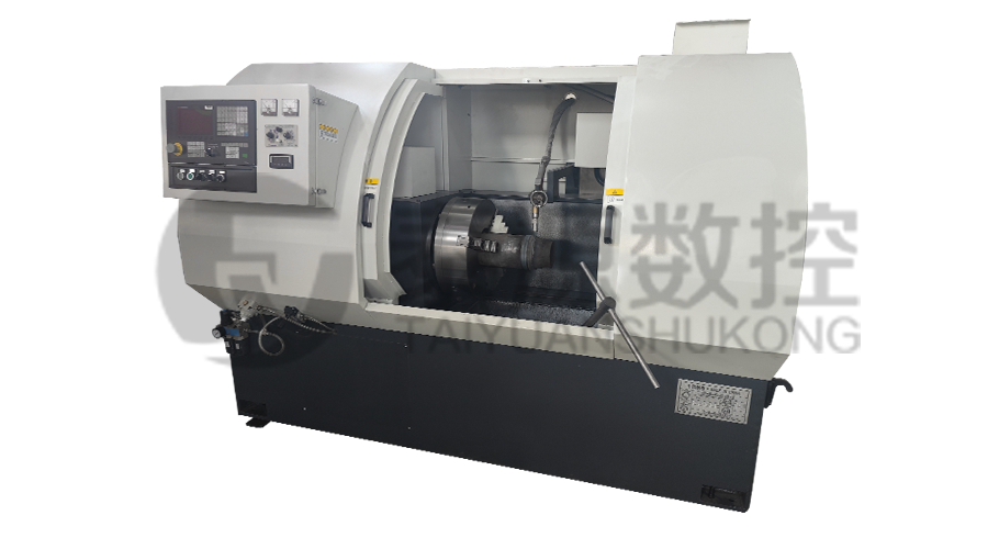 Series:TYSK-HB Semi-automatic wear-resistant band welder
Applicable to ARNCO 100XT, 200XT, 300XT. Support φ1.2-2.0 cored or solid wire surfacing welding.Can be equipped with single gun spray welding and double gun spray welding two ways. Support PLC or CNC system control.
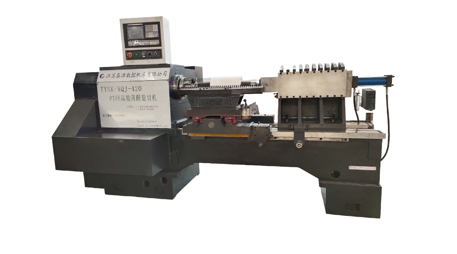 Model:TYSK-XQJ-550 Medium & Large PTFE Film Skiving Machine
Designed to process blanks with a maximum diameter of 550 mm and a maximum length of 1000 mm. We can also customize according to the needs of users. Friendly change speed and thickness with CNC.
