



 English
 عربى
 中文简体

Reminder information


Nov 18, 2026
Content
A threading lathe that swings 20-inch pipe can still be the wrong machine for 20-inch casing. The problem usually surfaces at the gauge bench, not on the shop floor: the coupling blanks will not pass the spindle bore, the taper drifts on the final passes, or the thread flanks tear because the tool is cutting at 50 rpm with too little torque behind it. None of those are machine defects. They are specification mismatches that were locked in months before the purchase order was signed.
The order of decisions that works is consistent across most large-diameter pipe shops: define the workpiece envelope and the thread standard first, then fix spindle bore and chuck capacity, then confirm rigidity and torque at threading speed, then agree on how thread accuracy will be proven, and only after that weigh automation and price. The sections below follow that sequence and list what is worth putting in writing.
Before you look at a single quotation, collect the numbers that describe the work itself. Each one removes options, and two of them decide the machine class on their own.
| Workpiece variable | Typical range in large-diameter work | What it constrains on the lathe |
|---|---|---|
| Pipe body OD | 4-1/2 in up to 20 in | Chuck size, swing over bed, steady rest range |
| Coupling or coupling stock OD | Always larger than the pipe body | Spindle bore when the part is fed through the headstock |
| Wall thickness | Heavy-wall casing and tool joints | Cutting force, torque at threading speed, insert grade |
| Joint length | Roughly 6 m to 13 m with the coupling fitted | Bed length, steady rest positions, tailstock travel |
| Joint weight | Up to several tonnes per joint | Loading method, foundation, chuck jaw clamping force |
| Thread specification | API 5B 8-round, API 5B buttress, premium connections | Tooling geometry, gauge set, program library |
The most common sizing error is a simple one. Pipe body OD gets used as the sizing number, coupling OD gets forgotten, and the machine arrives with a spindle bore that will pass the pipe but not the coupling. If your order book mixes pipe body threading with coupling work, size on the coupling and treat the pipe body as the easy case.
Spindle bore is the first figure to settle, because it is the one specification you cannot work around once the machine is installed. Everything else, including automation and tooling, can be added or upgraded later.
A workable rule is to keep 15 to 25 mm of radial clearance between the largest workpiece you intend to feed through the headstock and the bore wall. Tighter than that and the tube surface, the jaws and the bore itself become a handling risk, especially with a raw coupling blank that has not been cleaned or gauged. If the work cannot be fed through the bore, the machine has to be configured for front chucking with a steady rest, or for a bucking arrangement where the pipe is held stationary and the coupling is rotated.
For a closer look at how bore diameter interacts with draw tube size, bar capacity and maximum workpiece weight, see this note on spindle bore requirements for pipe threading machines.
The oil country class of lathe generally pairs a large bore with a wide bed, a heavy tailstock and long guideways, which is what allows a 13 m joint to be supported at both ends without the saddle losing contact. When you compare quotations, make the bore figure contractual, and ask whether it is measured cold with the draw tube installed, since some published numbers refer to the bare spindle.
Threading a heavy-wall coupling is closer to a roughing cut with a precision result than to a light finishing pass. On higher-strength grades, a single threading pass removes a wide, thick chip at low spindle speed, and the machine has to supply torque without stalling and stiffness without chattering.
Three specifications predict how the machine will behave in that cut: available torque at the spindle speeds actually used for threading, usually somewhere between 30 and 120 rpm; main spindle bearing bore and preload arrangement, which sets the chatter margin; and bed width with guideway type, which governs how the saddle behaves at the end of a long stroke. Worth asking for in writing:
Chatter is the failure mode to plan against. It starts as a faint mark on the flank, then shows up as pitch error once the tool deflects. A rigid setup with a properly positioned steady rest and minimum tool overhang usually matters more than an extra few kilowatts of spindle power.
Ask for a witnessed test cut using your material, your thread form and your gauge set. Catalogue accuracy statements are usually written for a short reference workpiece, not for a heavy-wall coupling threaded in one setup.
| Accuracy item | What the check proves | Instrument or method |
|---|---|---|
| Thread pitch diameter | The connection will make up to the correct standoff | API 5B ring or plug gauge with standoff measurement |
| Thread taper | Taper matches the form required by 8-round and buttress threads | Taper gauge or CMM on a sectioned sample |
| Thread height and form | Flank form and crest sit inside the standard envelope | Thread profile gauge or optical comparator |
| Cumulative lead over the full thread | Pitch error does not accumulate past the gauge limit | Lead checker or recorded linear axis verification |
| Flank finish and tearing | Cutting data and tooling suit the material being threaded | Roughness sample or profile measurement |
Record the test cut numbers and attach them to the contract. If a dispute arises six months later, the reference values matter more than any specification sheet.
A 20-inch casing joint can weigh well over two tonnes and reach beyond 12 m once a coupling is fitted. Crane loading is workable for a handful of joints per shift, but it becomes the bottleneck at production volumes and it puts an operator in the loop for every part. Before choosing between manual and automated loading, settle four questions:
Automation usually pays back on cycle time, but the larger return is on consistency. A machine that presents every joint to the same position removes an operator variable from thread accuracy, and that effect tends to show up in gauge rejection rates rather than in throughput figures.
A lathe that threads one coupling size perfectly can still be expensive to run if your order book spans six sizes. Changeover involves jaw sets, steady rest adjustment, program recall and gauge sets, and the gauge sets are often the largest hidden cost because they are bought per thread size and per connection type.
Quotations for the same nominal swing can differ by a wide margin, and the gap is usually explained by bed width, bearing class, guideway type, control platform and whether the machine is a general-purpose lathe adapted for pipe work or one designed around pipe threading from the start.
Most disputes in this equipment class come from numbers that were discussed verbally and never documented. A short list of commitments removes almost all of that risk:
The short version: size the machine on coupling OD and thread form, confirm torque at real threading speeds, insist on a witnessed test cut, and cost loading and changeover as part of the machine rather than as extras. Do those four things and the lathe will still be capable when the order book moves on to the next pipe size.
If you are still comparing configurations, the CNC machine tool range is a reasonable starting point for matching a machine class to your workpiece envelope before any detailed specification work begins.
Related Products
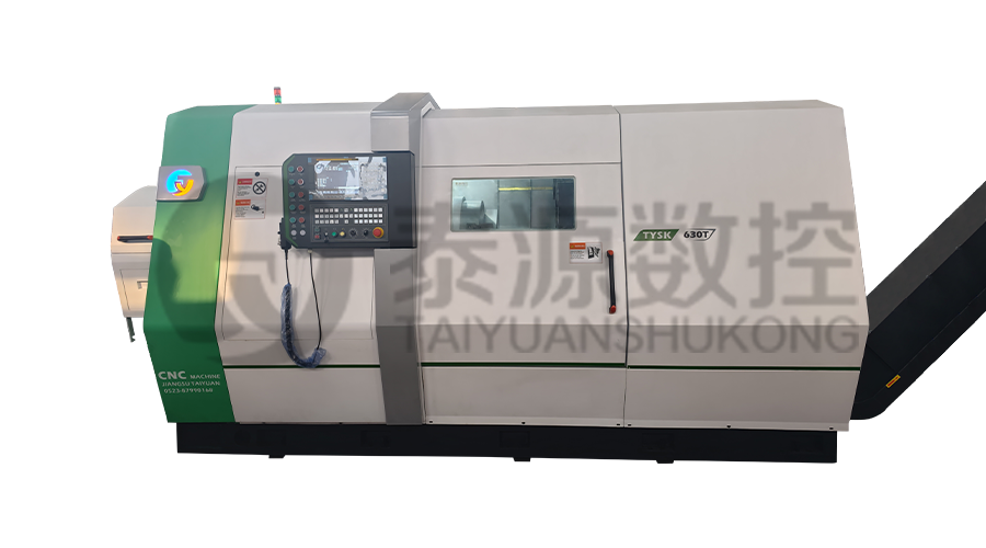 Model:TYSK-630T Drill Pipe, Joint & Coupling Lathe
The machine adopts a FANUC CNC system with stable processing accuracy and flexible programming functions to ensure that the processed parts meet strict industry standards. The high torque and heavy-load design can cope with long-term continuous work and has strong durability.
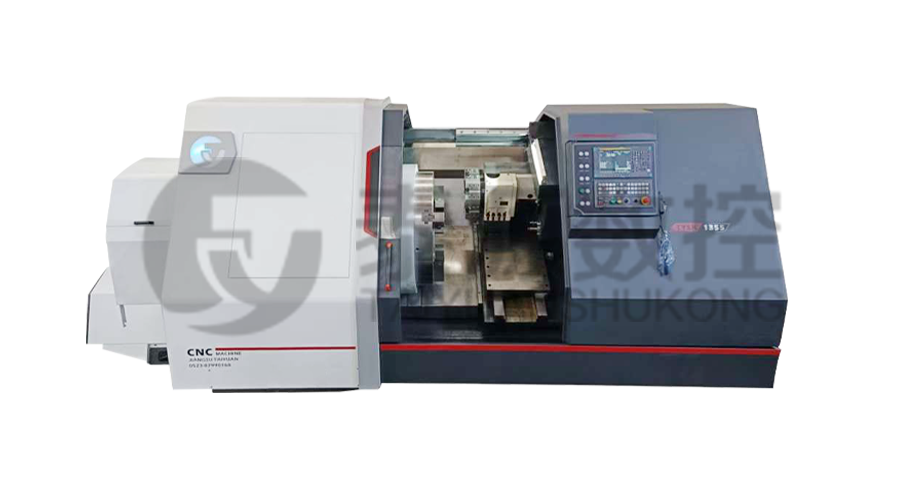 Model:TYSK-1355 Oil Pipe Processing Lathe
The machine adopts a FANUC CNC system with stable processing accuracy and flexible programming functions to ensure that the processed parts meet strict industry standards. The high torque and heavy-load design can cope with long-term continuous work and has strong durability.
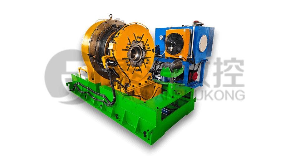 Series:TYSK-NKJ Screw-on machine/Casing and tubing coupling bucking unit
The machine uses a hydraulic motor, mechanical floating mechanism, and real-time torque detection, adapts to material bending, and prevents material deformation. Auxiliary machines are configured to help with semi-automation.
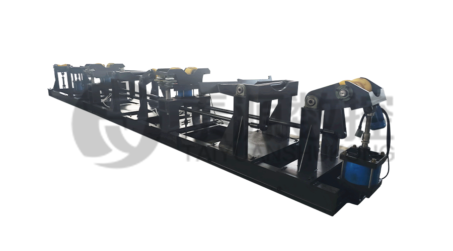 Long, heavy material solutions Automatic loading and unloading mechanism for pipe threading
The special flexible support mode can effectively reduce the influence of workpiece bending on processing and improve the yield. Strictly matching with our pipe threading lathe.
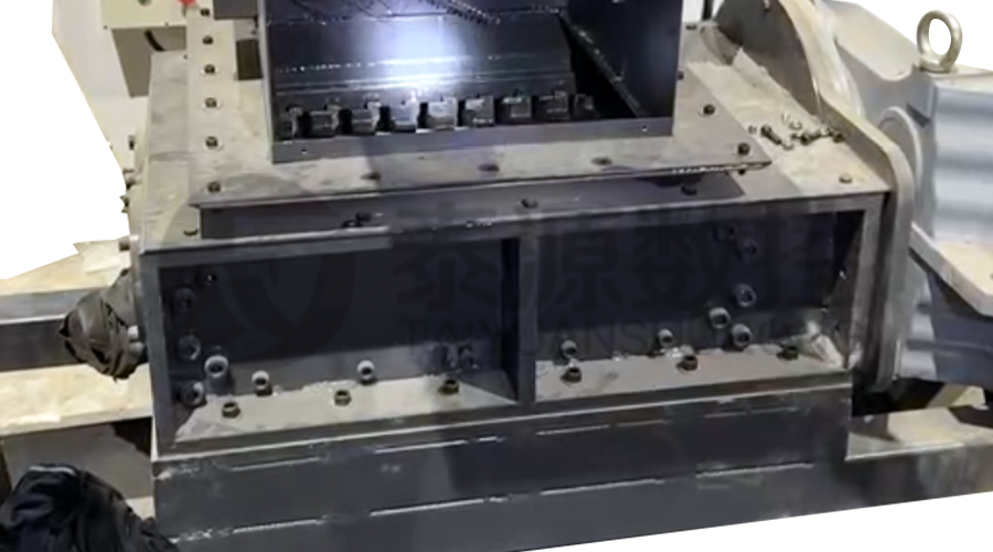 Modular Iron Chip Crusher High strength crusher for chip
The blades are made of high-strength materials and reasonably placed at the exit of the chip extractor to break the clump iron chips.Reduce the risk of rollback and improve waste frame utilization.
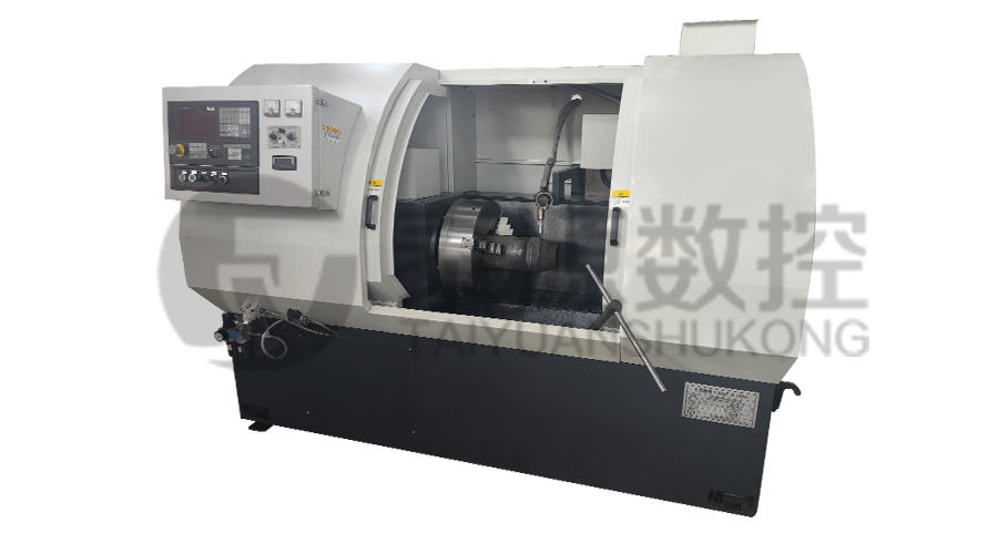 Series:TYSK-HB Semi-automatic wear-resistant band welder
Applicable to ARNCO 100XT, 200XT, 300XT. Support φ1.2-2.0 cored or solid wire surfacing welding.Can be equipped with single gun spray welding and double gun spray welding two ways. Support PLC or CNC system control.
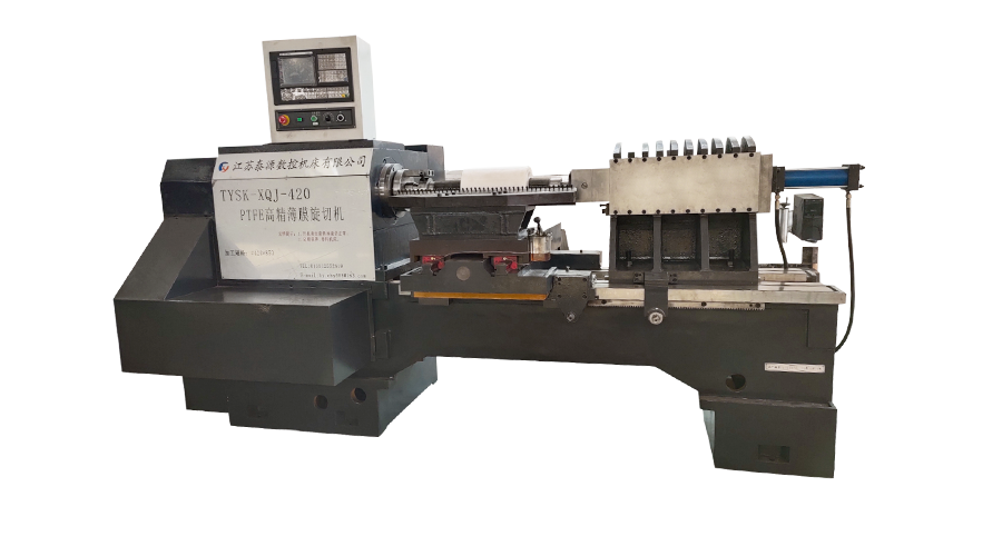 Model:TYSK-XQJ-550 Medium & Large PTFE Film Skiving Machine
Designed to process blanks with a maximum diameter of 550 mm and a maximum length of 1000 mm. We can also customize according to the needs of users. Friendly change speed and thickness with CNC.
