


 English
  عربى
عربى  中文简体
中文简体
Reminder information

Jun 25, 2026
Content
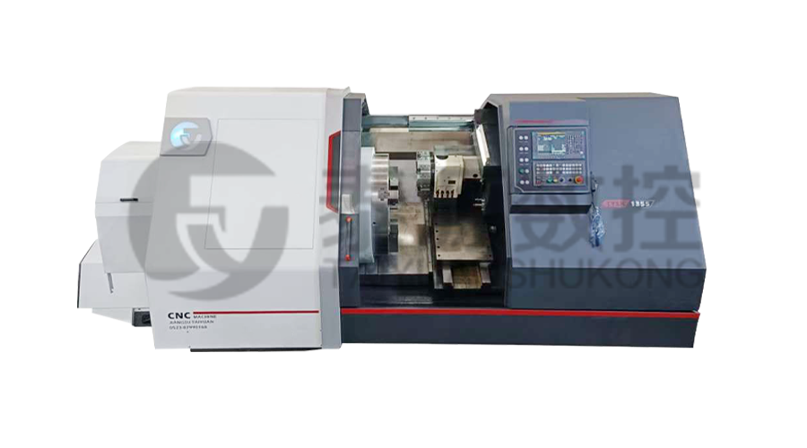
The Φ1000mm oil pipe processing lathe machine represents a purpose-built solution for oilfield tubular machining — combining a 1,000 mm swing-over-bed capacity with precision threading geometry, automated feed control, and robust construction engineered to handle API-grade oil country tubular goods (OCTG) at production scale.
A 1,000 mm swing diameter is the defining structural parameter of this lathe class. It determines the maximum outer diameter of workpiece that can rotate freely above the bed ways without interference. For oilfield applications, this accommodates large-diameter casing pipes, conductor pipes, and riser sections that conventional gap-bed lathes cannot process without extensive modification.
Beyond swing diameter, true Φ1000mm oil pipe machining capacity includes three interrelated specifications:
Threading accuracy on oil pipe lathes is measured against API Spec 5B tolerances, which define pitch diameter, taper, lead, and thread height limits for API round threads, buttress threads, and line pipe connections. The Φ1000mm platform achieves a pitch diameter tolerance of ±0.01 mm — tighter than the ±0.076 mm permitted under standard API 5B Class 1 gauging.
This precision is achieved through a combination of three engineering elements:
Oilfield tubular machining imposes requirements fundamentally different from general metalworking. Pipes are made from P110, Q125, or 13Cr stainless steel grades with hardness values reaching 34 HRC — materials that generate extreme cutting forces and accelerate tool wear. The Φ1000mm oil pipe processing lathe is built to sustain continuous throughput under these conditions.
Key structural features that sustain oilfield-grade performance include a Meehanite cast-iron bed with hardened and ground V-flat guideways, a spindle motor rated at 37–55 kW with variable-frequency drive, and a coolant system delivering 80 liters per minute at the cutting zone to manage chip evacuation and thermal load on hard-grade pipe material.
Modern Φ1000mm oil pipe lathes integrate CNC automation at multiple levels — reducing operator dependency, eliminating setup error, and directly cutting per-joint machining time. Key automation modules include:
Studies from oilfield tubular processing facilities in Texas and Alberta report cycle time reductions of 35–42% after transitioning from manual threading lathes to CNC-automated Φ1000mm platforms — with defect rates falling from 3.2% to under 0.4% per production run.
A conventional general-purpose lathe cannot substitute for a dedicated Φ1000mm oil pipe processing lathe machine in oilfield production. The differences are structural, not just dimensional.
| Specification | Φ1000mm Oil Pipe Lathe | Conventional Heavy Lathe |
| Threading standard compliance | API 5B / 5CT built-in gearbox | General metric/imperial only |
| Pipe steadyrest count | 4–8 hydraulic steadyrests | 1–2 manual steadyrests |
| Spindle bore | 130–160 mm | 80–105 mm |
| Hard material capability | Up to Q125 / 13Cr (HRC 34) | Up to 4140 alloy (HRC 26) |
| CNC automation level | Full CNC with ATC and gauging | Manual or semi-CNC |
| Shift throughput | 60–120 joints/shift | 15–30 joints/shift |
Related Products
 Model:TYSK-630T Drill Pipe, Joint & Coupling Lathe
The machine adopts a FANUC CNC system with stable processing accuracy and flexible programming functions to ensure that the processed parts meet strict industry standards. The high torque and heavy-load design can cope with long-term continuous work and has strong durability.
Model:TYSK-1355 Oil Pipe Processing Lathe
The machine adopts a FANUC CNC system with stable processing accuracy and flexible programming functions to ensure that the processed parts meet strict industry standards. The high torque and heavy-load design can cope with long-term continuous work and has strong durability.
 Series:TYSK-NKJ Screw-on machine/Casing and tubing coupling bucking unit
The machine uses a hydraulic motor, mechanical floating mechanism, and real-time torque detection, adapts to material bending, and prevents material deformation. Auxiliary machines are configured to help with semi-automation.
 Long, heavy material solutions Automatic loading and unloading mechanism for pipe threading
The special flexible support mode can effectively reduce the influence of workpiece bending on processing and improve the yield. Strictly matching with our pipe threading lathe.
 Modular Iron Chip Crusher High strength crusher for chip
The blades are made of high-strength materials and reasonably placed at the exit of the chip extractor to break the clump iron chips.Reduce the risk of rollback and improve waste frame utilization.
 Series:TYSK-HB Semi-automatic wear-resistant band welder
Applicable to ARNCO 100XT, 200XT, 300XT. Support φ1.2-2.0 cored or solid wire surfacing welding.Can be equipped with single gun spray welding and double gun spray welding two ways. Support PLC or CNC system control.
 Model:TYSK-XQJ-550 Medium & Large PTFE Film Skiving Machine
Designed to process blanks with a maximum diameter of 550 mm and a maximum length of 1000 mm. We can also customize according to the needs of users. Friendly change speed and thickness with CNC.
