



 English
 عربى
 中文简体

Reminder information


Oct 21, 2026
Content
Ten joints into a casing coupling run, a threading operator checks standoff with a gauge, gets a clean reading, and then finds the twelfth piece out of tolerance. On a conventional lathe that drift is almost always mechanical: a warm headstock, a lead screw worn unevenly along its length, a half-nut that engaged one thread late. On a CNC pipe threading lathe, the same drift shows up as a number on a screen and is corrected with a parameter change.
That single contrast explains why the choice between these two machine types matters far more in oil pipe processing than in general turning. A conventional lathe can cut a thread on a pipe, and for short, low-pressure, non-critical work it still does the job well. But once the pipe has to pass through the headstock, the thread has to hold an API 5B tolerance band, and the batch runs into the hundreds, the two machines stop being interchangeable.
Nearly every practical difference between these machines falls into four buckets:
Control brand, chip conveyor capacity and coolant tank size all sit downstream of those four points.
Start with arithmetic, not brochures. A 4-1/2 in casing has an outside diameter of 114.3 mm, so a machine expected to thread it through the spindle needs a clear bore comfortably above that figure once jaw thickness and liner clearance are counted. Move up to 7 in casing at 177.8 mm, or 9-5/8 in, and the requirement climbs quickly.
Most conventional lathes are built with spindle bores between roughly 40 mm and 100 mm, because they are designed for shaft work held between centres rather than for pipe that must pass through. On those machines, threading both ends of a joint usually means chucking on the OD, cutting one thread, flipping the pipe, and dialling it back in. Every one of those steps adds runout, and runout shows up later as taper error and standoff variation. That is why bore capacity, not control type, is often the first filter in pipe shop planning. If you are comparing specifications, spindle bore requirements for pipe threading machines breaks the sizing logic down in more detail.
On a conventional lathe, the relationship between spindle rotation and carriage travel is mechanical. The spindle drives a lead screw through a gear train, the operator engages a half-nut at the right moment on the thread chasing dial, and the tool follows the pitch the gears dictate. It works, but every link in that chain contributes error. A lead screw worn 0.05 mm over its length cuts a thread that is slightly tight near the headstock and slightly loose further out. Thermal growth in a warm headstock changes the effective ratio during a shift.
A CNC pipe threading lathe replaces that chain with an electronic one. Spindle and Z axis are synchronized by the control, so the tool can enter the thread at any point along the pipe, which is what makes thread repair on a used joint practical rather than a gamble. It also means pitch error compensation, taper interpolation for API 1:16 threads, and consistent buttress or multi-start profiles from the first piece to the last. For coupling and bucking work, that consistency is usually what justifies the price difference.
Oil pipe is not clean, uniform stock. Welded seam pipe presents a hard spot once per revolution. Heavy-wall and upset ends demand high cutting torque at low speed. Hardbanded sections interrupt the cut entirely. On a lighter conventional lathe those conditions produce chatter, and chatter leaves its signature on the thread flank as roughness that a profile gauge will find.
Threading machines for this work are built around stiffness: wide box ways, a heavily ribbed bed, large spindle bearings, and a spindle motor sized for low-speed torque rather than peak speed. The practical test is simple. Cut a thread on the heaviest wall section in your range and inspect the flank. If the machine runs quiet and the surface is uniform, the structure is doing its job.
| Consideration | CNC pipe threading lathe | Conventional lathe |
|---|---|---|
| Spindle through-bore | Sized for pipe from roughly 4-1/2 in upward | Typically 40 to 100 mm, suits small tube and shaft work |
| Thread synchronization | Spindle and Z axis linked electronically | Lead screw, gear train and half-nut |
| Pitch accuracy over long threads | Compensated and repeatable | Drifts with screw wear and temperature |
| Thread repair on a used joint | Any start point, on the machine | Difficult, often needs re-chucking |
| Size changeover | Program change plus jaw and steady-rest change | Gear change and re-indication, longer setup |
| Batch repeatability | High, largely independent of operator rhythm | Depends strongly on operator skill and attention |
| Best fit | Coupling and joint shops, API-regulated threads | Repair work, short nipples, non-critical threads |
The table is a starting point rather than a verdict. Two machines with the same control can behave very differently depending on bed stiffness and spindle bearing class, and two shops with identical pipe ranges can reach opposite conclusions depending on batch size.
It would be wrong to write the conventional lathe off. For a shop cutting short nipples, adaptors, water and air line fittings, or repairing a single joint pulled from a workover, a conventional lathe is cheaper to buy, simpler to maintain and quicker to set up for one-off work. It also needs less floor space and no programmer.
The line to draw is the consequence of failure. If the thread goes downhole under pressure and must pass a coupling torque test, the tolerance band is narrow enough that manual thread chasing becomes a liability. If the thread simply has to hold, the manual machine is fine.
A 9-5/8 in casing joint is heavy, and lifting it in and out of a chuck with a crane all day is both slow and tiring. That is why threading lines for oil pipe usually pair the lathe with power steady rests, hydraulic chucks and an automatic loading and unloading mechanism. Once handling is automated, one operator can run more than one machine, and cycle time stops being limited by how fast someone can swing a joint into position.
Chip handling deserves equal attention. Pipe threading produces long, stringy steel swarf that wraps around the tool and the workpiece if it is not broken and evacuated. A chip breaker or crusher in the swarf path, plus a properly sized conveyor, prevents the kind of interruption that ruins a thread halfway through a cut.
Answer these questions in writing before requesting quotations:
If the answers point to a wide diameter range, API threads and continuous batches, a purpose-built oil pipe processing lathe is the right starting point rather than a general-purpose turning machine.
The most useful step before buying either machine type is an acceptance test on your own pipe, not the demonstrator's stock. Bring three joints of the heaviest wall you run, cut threads on all of them, and measure standoff, pitch diameter and taper with the gauges your customer will use. Then cut the same thread twenty times and check the spread. A machine that holds the tolerance band across twenty pieces without operator adjustment earns its price; one that needs a tweak every few pieces will cost you in rework and re-inspection. If you want a closer look at how our machine tool range is configured for tubular work, the specification sheets will tell you more than a general catalogue will.
Related Products
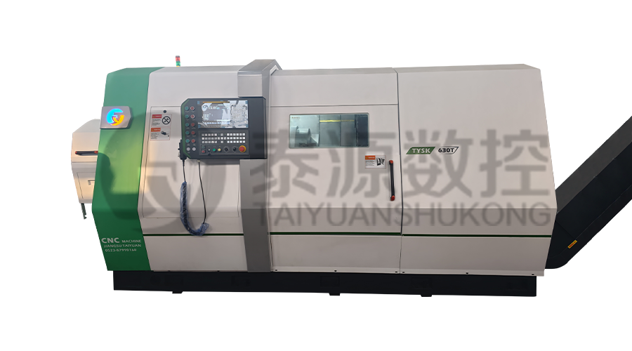 Model:TYSK-630T Drill Pipe, Joint & Coupling Lathe
The machine adopts a FANUC CNC system with stable processing accuracy and flexible programming functions to ensure that the processed parts meet strict industry standards. The high torque and heavy-load design can cope with long-term continuous work and has strong durability.
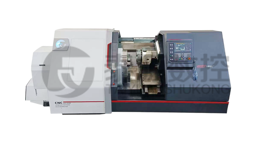 Model:TYSK-1355 Oil Pipe Processing Lathe
The machine adopts a FANUC CNC system with stable processing accuracy and flexible programming functions to ensure that the processed parts meet strict industry standards. The high torque and heavy-load design can cope with long-term continuous work and has strong durability.
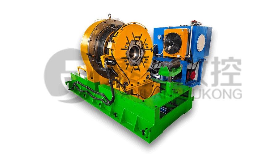 Series:TYSK-NKJ Screw-on machine/Casing and tubing coupling bucking unit
The machine uses a hydraulic motor, mechanical floating mechanism, and real-time torque detection, adapts to material bending, and prevents material deformation. Auxiliary machines are configured to help with semi-automation.
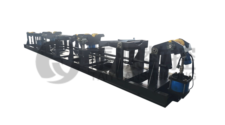 Long, heavy material solutions Automatic loading and unloading mechanism for pipe threading
The special flexible support mode can effectively reduce the influence of workpiece bending on processing and improve the yield. Strictly matching with our pipe threading lathe.
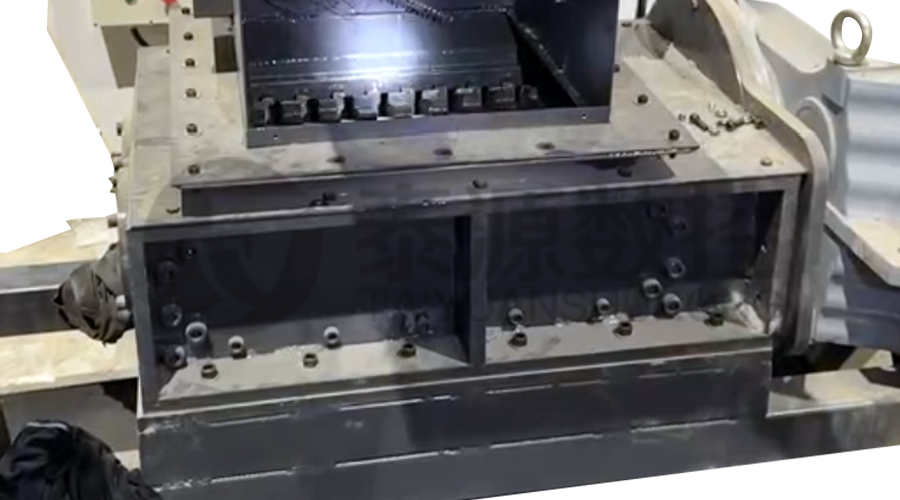 Modular Iron Chip Crusher High strength crusher for chip
The blades are made of high-strength materials and reasonably placed at the exit of the chip extractor to break the clump iron chips.Reduce the risk of rollback and improve waste frame utilization.
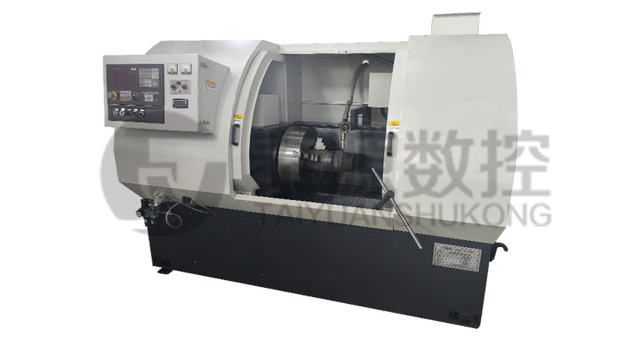 Series:TYSK-HB Semi-automatic wear-resistant band welder
Applicable to ARNCO 100XT, 200XT, 300XT. Support φ1.2-2.0 cored or solid wire surfacing welding.Can be equipped with single gun spray welding and double gun spray welding two ways. Support PLC or CNC system control.
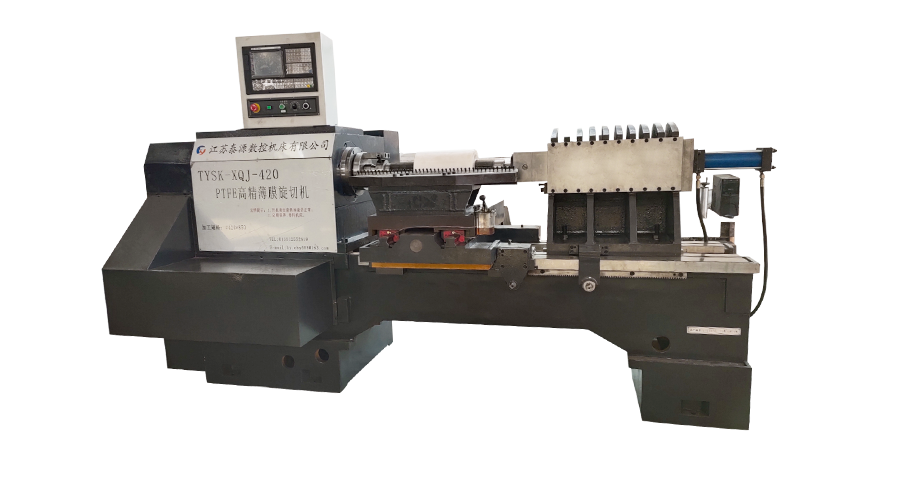 Model:TYSK-XQJ-550 Medium & Large PTFE Film Skiving Machine
Designed to process blanks with a maximum diameter of 550 mm and a maximum length of 1000 mm. We can also customize according to the needs of users. Friendly change speed and thickness with CNC.
