



 English
  عربى
عربى  中文简体
中文简体

Reminder information

Oct 14, 2026
Content
Three 6-3/4 in drill collars scrapped in one week usually share the same cause: the bore drifted in the last meter, wall thickness ran out of tolerance, and the bar could not be recovered. That is normally when a shop starts comparing deep hole drilling machines for drill collars seriously. Drilling a collar bore is not ordinary drilling with a longer tool. It is a separate process with its own machine architecture, coolant pressures measured in tens of bar, and acceptance criteria written around bore straightness, wall thickness variation, and bore finish rather than hole position.
The conclusion first: fix four numbers before looking at any machine. Largest bore diameter, longest single-pass depth, the length-to-diameter ratio you must hold in production, and the weight of the bar you intend to load. Spindle power, bed length, coolant package, and automation level follow from those four. They are not starting points.
A drill collar is a thick-walled seamless bar, normally 4145H modified steel heat treated to roughly 285-341 HB. Finished lengths sit near 9.1 m (30 ft) or 9.5 m (31 ft), outside diameters run from about 4-3/4 in to 11 in, and the through bore is commonly between 50 mm and 100 mm. That combination produces length-to-diameter ratios from roughly 80:1 to 180:1, well past the point where a twist drill or a standard indexable insert drill stays straight.
Three requirements drive the machine specification:
API Spec 7-1 sets the dimensional framework for drill collars, but most operators add their own limits on straightness, wall variation, and bore finish. Those added limits, not the standard alone, are what the machine has to satisfy.
Deep hole capacity on a collar line rarely serves one product. In practice the same machine usually covers:
If more than one category is planned, size the diameter and depth envelope for the largest of them rather than the average. Adding 25 mm of bore capacity at the order stage costs far less than replacing a machine two years later.
Method selection comes before machine selection, because it fixes the coolant path, the pressure, and the tooling family. All three methods are self-piloting and use counter-rotation; they differ mainly in how chips leave the cut.
| Method | Typical bore range | Chip evacuation | Coolant pressure | Notes for drill collar work |
|---|---|---|---|---|
| Gun drilling | 3-50 mm | External, along a V-shaped flute | 30-100 bar | Strong straightness in small bores; practical as a pilot pass before a larger bore |
| BTA (STS) | 16-100 mm and above | Internal, through the tube | 20-60 bar, high flow | Highest metal removal rate; the usual route for 50-100 mm collar bores |
| Ejector | 20-180 mm | Internal, venturi-assisted | 10-40 bar | Lower pressure demand, useful where pump capacity is limited |
For a 50-100 mm collar bore, BTA or ejector is normally the production route, with gun drilling reserved for smaller pilots. One detail decides more projects than any other: coolant volume scales with bore diameter, not just pressure. A system holding 60 bar on a 20 mm hole can be starved on a 90 mm bore.
Quote the machine against a working envelope, not a maximum figure. A machine with 1500 mm of stroke but only 3000 mm of usable bed will not drill a 9.1 m collar in one pass. Ask for maximum single-pass depth with the workpiece supported, and confirm that the same value applies at the largest bore diameter, since torque and coolant demand both rise with diameter.
This is where deep hole projects lose time. Specify pressure at the tool, flow in liters per minute at that pressure, and filtration rating together. Filtration in the 10-25 micron range is common for BTA work, and the chip separation system must handle the volume produced at maximum removal rate without a mid-shift tank clean. Undersized filtration shows up as inconsistent bore finish and chipped tool edges long before the pump fails.
A 9.5 m, 1000 kg collar cannot be hand-loaded repeatedly or safely. Steady rest arrangement, guide bush design, and loading method set both real cycle time and operator risk. Hydraulic steady rests with independent adjustment, hardened guide bushes matched to the pilot diameter, and a mechanical or automated loading arrangement for long heavy bars belong in the specification from the start.
Ask for a witness cut. The cleanest test is a full-length bore in a bar of the same grade and hardness, followed by measurement of straightness, wall thickness variation at intervals, and bore finish. Alignment between headstock, guide bush, and steady rest should be documented and re-checkable with a test bar. A machine that meets tolerance when new but cannot be realigned in the field will drift out of tolerance within a few years.
The bore is only the first operation. Once the hole is established, the collar still needs OD turning to size, taper machining, shoulder facing, and connection threads cut and gauged, and those operations carry their own accuracy demands because thread and shoulder take the make-up load. Shops that plan the whole route at once keep bore concentricity figures in front of the turning and threading group, so the second operation does not chase an error the first one created.
For the turning stage, a heavy-duty oil country lathe with a wide bed, generous swing, and a spindle bore able to pass the collar body is the usual configuration.
Joint and coupling thread cutting is a separate machine class again, with its own pitch accuracy, taper, and gauge requirements.
Material handling ties the line together, and the loading arrangement chosen for long heavy bars often decides whether the line runs at the cycle times its machines are capable of.
Where the collar route also includes pipe-end work, a drill pipe joint coupling lathe guide is a useful cross-check on how turning and threading stages are normally specified together, and platform-level information on CNC pipe threading lathes helps when the same bay has to handle both collars and tubulars.
Deep hole drilling machines for drill collars are chosen by envelope and coolant, not by spindle power alone. Pin down bore diameter, single-pass depth, length-to-diameter ratio, and bar weight first; size pressure, flow, filtration, and loading around those; then verify the result with a full-length witness cut in real material. That sequence keeps the machine matched to the work, and it keeps the turning and threading stages downstream from inheriting a bore error they cannot correct.
Related Products
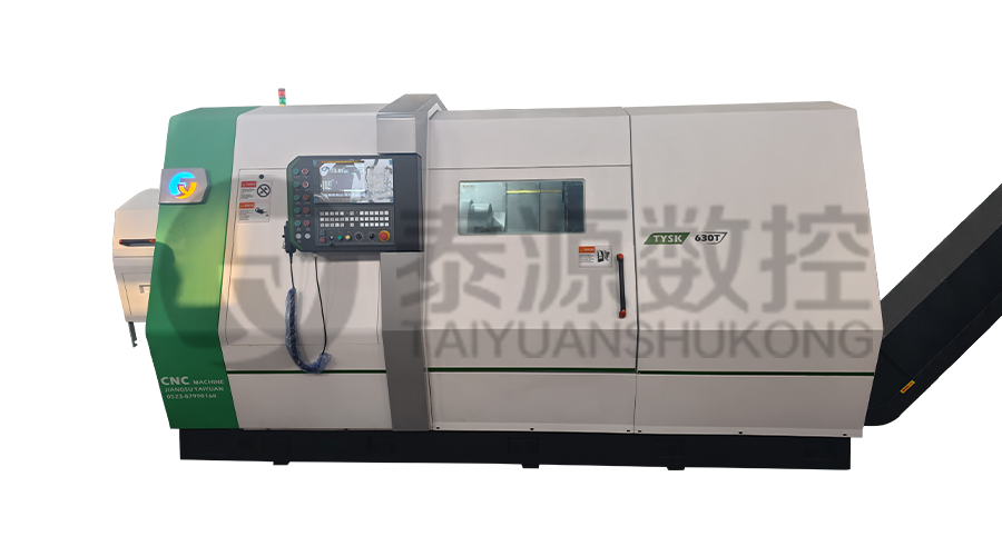 Model:TYSK-630T Drill Pipe, Joint & Coupling Lathe
The machine adopts a FANUC CNC system with stable processing accuracy and flexible programming functions to ensure that the processed parts meet strict industry standards. The high torque and heavy-load design can cope with long-term continuous work and has strong durability.
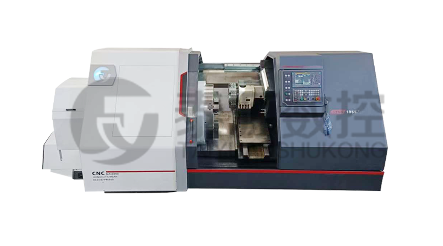 Model:TYSK-1355 Oil Pipe Processing Lathe
The machine adopts a FANUC CNC system with stable processing accuracy and flexible programming functions to ensure that the processed parts meet strict industry standards. The high torque and heavy-load design can cope with long-term continuous work and has strong durability.
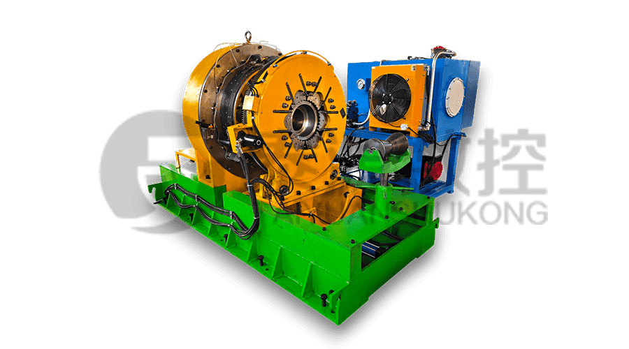 Series:TYSK-NKJ Screw-on machine/Casing and tubing coupling bucking unit
The machine uses a hydraulic motor, mechanical floating mechanism, and real-time torque detection, adapts to material bending, and prevents material deformation. Auxiliary machines are configured to help with semi-automation.
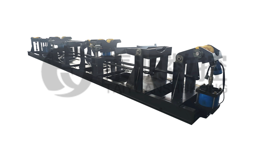 Long, heavy material solutions Automatic loading and unloading mechanism for pipe threading
The special flexible support mode can effectively reduce the influence of workpiece bending on processing and improve the yield. Strictly matching with our pipe threading lathe.
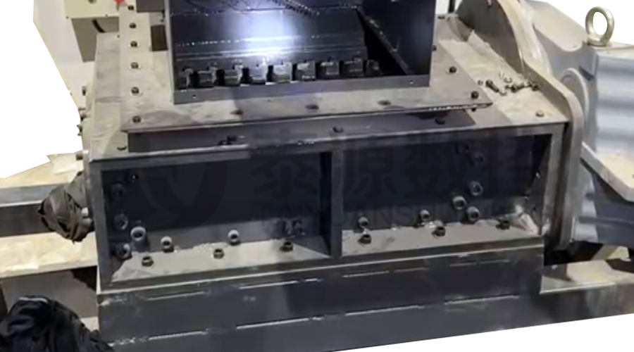 Modular Iron Chip Crusher High strength crusher for chip
The blades are made of high-strength materials and reasonably placed at the exit of the chip extractor to break the clump iron chips.Reduce the risk of rollback and improve waste frame utilization.
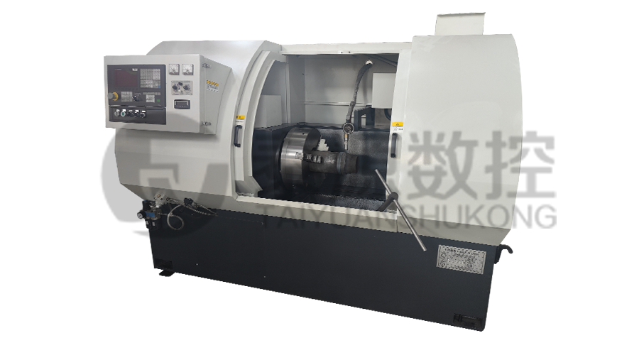 Series:TYSK-HB Semi-automatic wear-resistant band welder
Applicable to ARNCO 100XT, 200XT, 300XT. Support φ1.2-2.0 cored or solid wire surfacing welding.Can be equipped with single gun spray welding and double gun spray welding two ways. Support PLC or CNC system control.
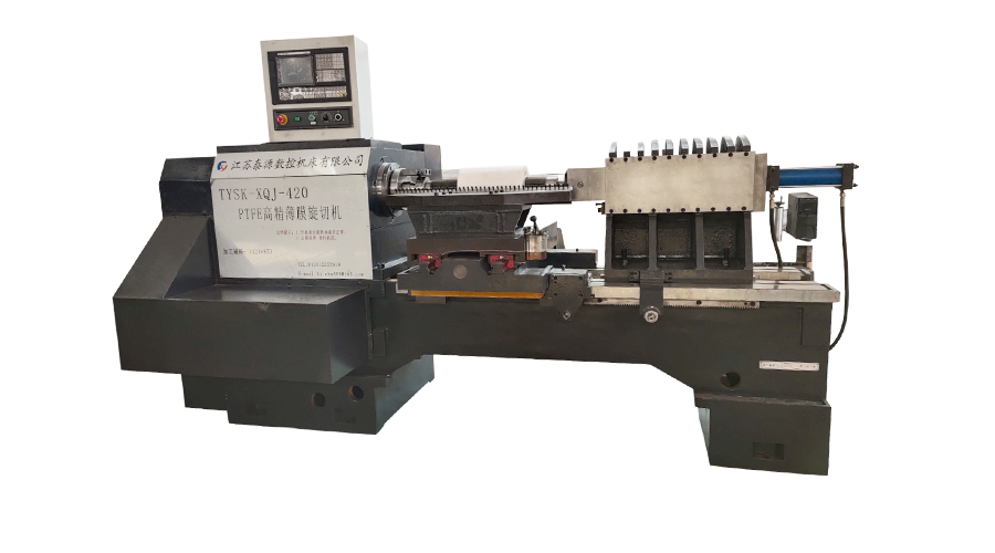 Model:TYSK-XQJ-550 Medium & Large PTFE Film Skiving Machine
Designed to process blanks with a maximum diameter of 550 mm and a maximum length of 1000 mm. We can also customize according to the needs of users. Friendly change speed and thickness with CNC.
