



 English
  عربى
عربى  中文简体
中文简体

Reminder information

Jul 09, 2026
Content
An automatic loading and unloading mechanism for pipe threading is the equipment layer that moves raw pipe stock into a threading machine and removes finished pieces without manual handling. It has become a core building block of modern pipe processing lines because it removes repetitive labor, tightens positioning accuracy, and keeps a threading machine running at a steady, predictable pace shift after shift.
An automatic loading and unloading mechanism for pipe threading is a mechanical and electronic system that transfers pipe sections into a threading machine's working position, holds them during the cutting or rolling operation, and then transfers the finished pipe out to a collection area. The system typically works in three coordinated stages: feeding raw stock from a storage rack or magazine, aligning and clamping the pipe at the correct centerline for threading, and discharging the completed part once the spindle or die head finishes its pass.
This is a pipe threading automation system in the truest sense: sensors detect pipe presence and diameter, a controller sequences the clamping and feeding actions, and the threading head only engages once the pipe is confirmed to be seated correctly. This is why an automatic pipe loading system reduces both cycle time and the chance of a misthreaded part compared with an operator manually positioning each pipe by hand.
Pipe processing plants use several distinct mechanism families, each suited to different pipe sizes, production volumes, and factory layouts. A robotic pipe feeder system uses an articulated or gantry-style arm to pick pipes from a rack and place them directly into the machine chuck, which suits mixed batch sizes and frequent product changeovers. A conveyor pipe loading mechanism moves stock along a belt or roller track toward the machine, which suits high-volume runs of similar pipe diameters. A hydraulic pipe handling system uses hydraulic cylinders to lift, tilt, or push pipes into position, favored where heavier pipe sections need controlled, high-force movement. A gantry loading unloading device spans the work area on an overhead frame and is common in long-pipe processing lines. A magazine type pipe feeding system stores pre-sorted pipes in a rack and releases them one at a time, which works well for standardized diameters in continuous production.
| Mechanism Type | Best Suited For | Typical Advantage |
| Robotic pipe feeder | Mixed batch sizes, frequent changeovers | Flexibility across pipe diameters |
| Conveyor loading mechanism | High-volume, similar diameter runs | Continuous throughput |
| Hydraulic handling system | Heavier or thicker-wall pipe sections | Controlled high-force movement |
| Gantry loading unloading device | Long pipe processing lines | Wide reach over the work area |
| Magazine type feeding system | Standardized diameters, continuous runs | Simple, low-complexity feeding |
Automatic pipe loading and unloading mechanisms are used anywhere pipe threading happens at repeatable volume. Steel pipe manufacturing plants use them on finishing lines where every pipe leaving the mill needs a threaded end before shipment. Oil and gas pipe processing lines rely on them to keep casing and tubing threading consistent, since thread quality directly affects joint sealing in the field. Construction pipe fabrication workshops use smaller-footprint versions for job-lot orders of varying pipe lengths. Industrial CNC machining centers integrate these mechanisms directly into automated cells alongside other machining operations. Pipeline equipment production facilities use them on dedicated threading stations that feed downstream assembly of fittings and couplings.
A dependable pipe threading loading system is judged on how consistently it positions pipe and how little it interrupts production. A high precision pipe alignment system keeps every pipe centered on the same axis so the die head engages the same way each time. Fast cycle time automation equipment shortens the gap between one finished pipe leaving and the next raw pipe arriving. A stable pipe positioning mechanism holds the pipe firmly during the entire threading pass so vibration does not distort the thread profile. Heavy load handling capacity lets the system manage longer or thicker-wall pipe sections without added strain on the drive components. Continuous production efficiency ties these properties together, letting a line run for extended periods with minimal operator intervention.
Building an automatic loading and unloading mechanism for pipe threading follows a structured engineering path from concept to a working production cell.
Engineers document the range of pipe diameters, lengths, and wall thicknesses the mechanism must handle before any drawing work begins.
The feeding, clamping, and discharge paths are laid out, along with the structural steel frame fabrication that will support the moving components.
A PLC industrial control system is paired with a servo motor control system to sequence motion, while a hydraulic clamping mechanism is sized for the expected pipe weight.
The frame, drive components, and sensors are built and assembled, then wired into the control cabinet for the target threading machine.
The mechanism runs sample pipe through full load-thread-unload cycles so alignment tolerances and timing sequences can be fine-tuned before handover.
Manual vs automatic pipe handling comes down to labor demand, consistency, and safety exposure. A manual system depends entirely on operator attention for every pipe placed and removed, which introduces variability from one cycle to the next. An automated mechanism repeats the same motion path every time, which is why consistency in machining operations improves once automation is introduced.
No automation system is free of operating challenges, and pipe threading mechanisms have a known set of failure points that maintenance teams watch closely.
| Issue | Typical Cause | Operational Impact |
| Pipe misalignment | Worn guide rollers or loose fixturing | Inconsistent thread engagement |
| Sensor calibration errors | Sensor drift or debris on detection surfaces | False stops or missed pipe detection |
| Mechanical wear on feeding rollers | Continuous friction contact over time | Reduced grip and slower feed accuracy |
| System synchronization failure | Timing mismatch between control and mechanical motion | Collisions or missed handoff cycles |
| Maintenance complexity | Multiple integrated subsystems (hydraulic, servo, PLC) | Longer diagnostic time when faults occur |
These limitations are manageable with scheduled inspection routines, but they explain why an automation system for pipe threading is only as reliable as the maintenance plan built around it.
The direction of pipe threading automation is toward systems that do not just move pipe, but also monitor and adjust their own performance during production.
Smart factory automation systems are increasingly connecting pipe loading mechanisms into plant-wide production data networks, so a threading cell's output feeds directly into scheduling and quality tracking. AI-based industrial control systems are being explored to help mechanisms adapt feed speed and clamping force based on the specific pipe batch being processed. Robotic manufacturing integration continues to expand as robotic arms take on more of the loading and unloading role previously handled by fixed conveyors or gantries. Predictive maintenance machinery is another growing trend, using sensor data trends to flag wear before a breakdown occurs. Together these developments point toward fully automated production lines where pipe threading is one seamless stage within a larger connected manufacturing process.
It is a mechanized system that feeds pipe stock into a threading machine and removes finished pipe automatically, without an operator handling each piece by hand.
Sensors and a controller coordinate feeding, clamping, and threading so the pipe is positioned correctly before the threading head engages, then the finished piece is discharged automatically.
Automation generally delivers more consistent alignment and keeps operators away from the active threading zone, while manual feeding depends more heavily on operator skill and attention.
Steel pipe manufacturing, oil and gas processing, construction fabrication, CNC machining centers, and pipeline equipment production all rely on pipe threading machines.
Yes, mechanisms are commonly engineered around a plant's specific pipe diameter range, length variation, and required production cycle time.
It refers to pairing a CNC-controlled threading machine with an automated loading and unloading mechanism so the entire threading cycle runs with minimal manual input.
Related Products
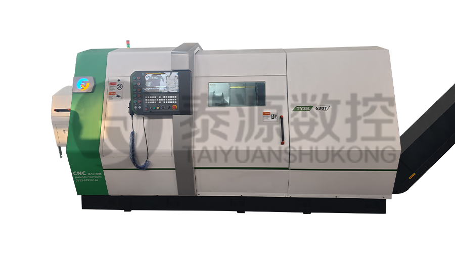 Model:TYSK-630T Drill Pipe, Joint & Coupling Lathe
The machine adopts a FANUC CNC system with stable processing accuracy and flexible programming functions to ensure that the processed parts meet strict industry standards. The high torque and heavy-load design can cope with long-term continuous work and has strong durability.
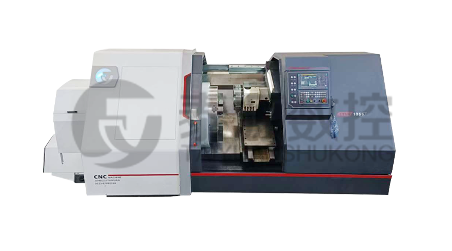 Model:TYSK-1355 Oil Pipe Processing Lathe
The machine adopts a FANUC CNC system with stable processing accuracy and flexible programming functions to ensure that the processed parts meet strict industry standards. The high torque and heavy-load design can cope with long-term continuous work and has strong durability.
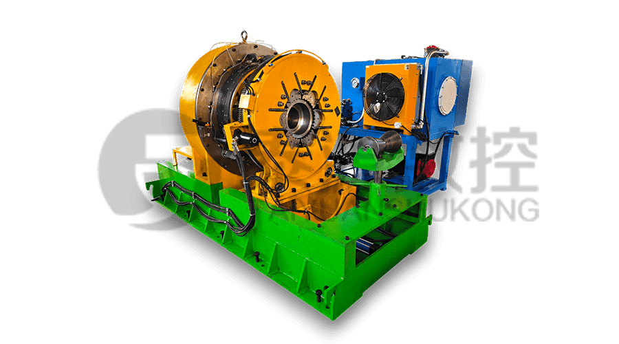 Series:TYSK-NKJ Screw-on machine/Casing and tubing coupling bucking unit
The machine uses a hydraulic motor, mechanical floating mechanism, and real-time torque detection, adapts to material bending, and prevents material deformation. Auxiliary machines are configured to help with semi-automation.
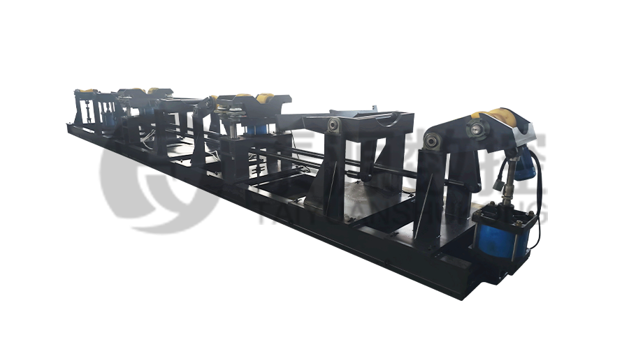 Long, heavy material solutions Automatic loading and unloading mechanism for pipe threading
The special flexible support mode can effectively reduce the influence of workpiece bending on processing and improve the yield. Strictly matching with our pipe threading lathe.
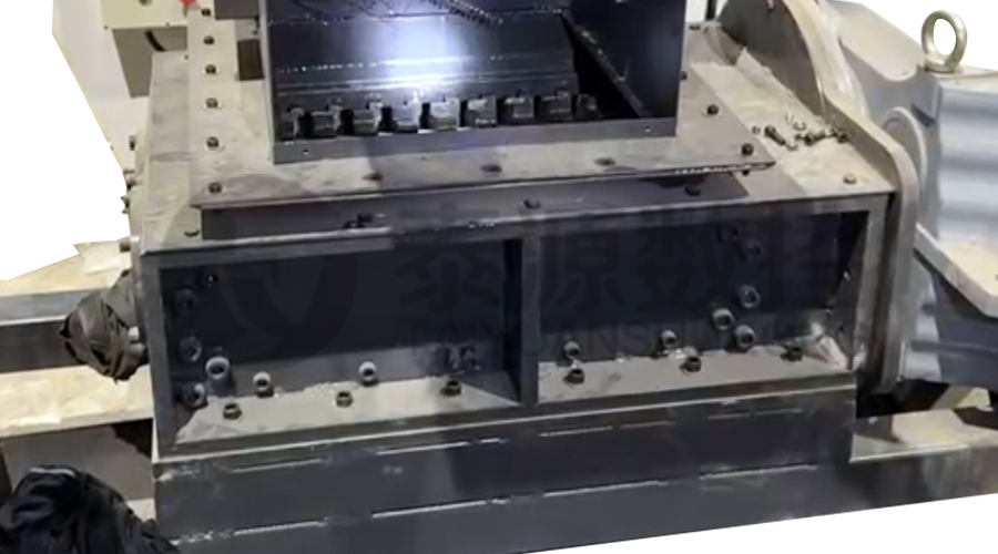 Modular Iron Chip Crusher High strength crusher for chip
The blades are made of high-strength materials and reasonably placed at the exit of the chip extractor to break the clump iron chips.Reduce the risk of rollback and improve waste frame utilization.
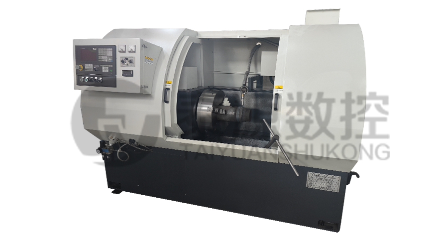 Series:TYSK-HB Semi-automatic wear-resistant band welder
Applicable to ARNCO 100XT, 200XT, 300XT. Support φ1.2-2.0 cored or solid wire surfacing welding.Can be equipped with single gun spray welding and double gun spray welding two ways. Support PLC or CNC system control.
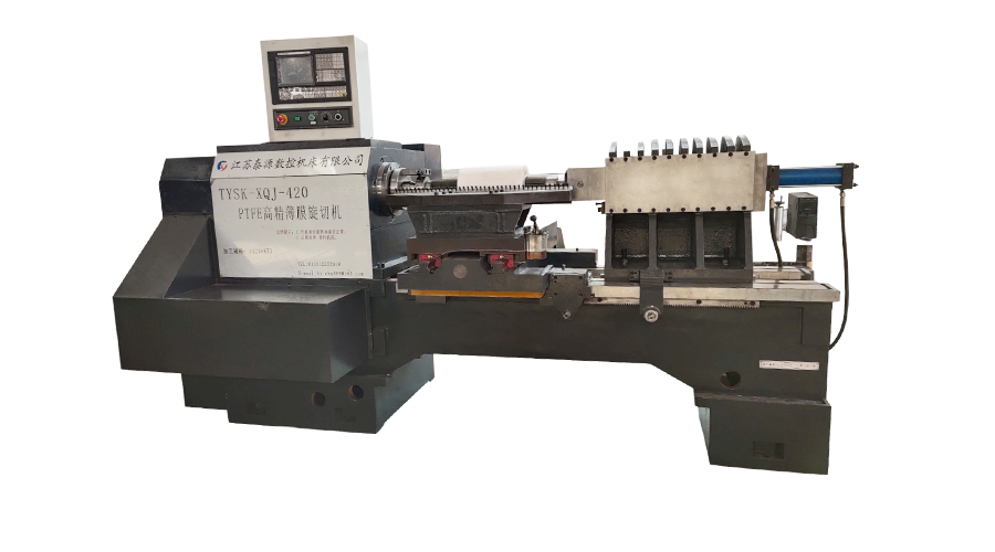 Model:TYSK-XQJ-550 Medium & Large PTFE Film Skiving Machine
Designed to process blanks with a maximum diameter of 550 mm and a maximum length of 1000 mm. We can also customize according to the needs of users. Friendly change speed and thickness with CNC.
