


 English
  عربى
عربى  中文简体
中文简体
Reminder information

Jun 11, 2026
Content
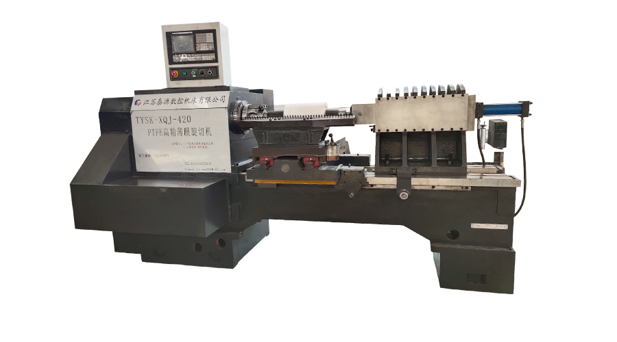
The medium & large PTFE film skiving machine is the production-grade solution for converting sintered PTFE billets into continuous thin-film tape at industrial scale. Unlike smaller bench-top units, medium and large configurations handle billet diameters exceeding 300 mm, support wide-format roll output up to 1,600 mm, and sustain cutting precision of ±0.005 mm across extended production runs. This guide covers thickness capability, roll fitment, speed calibration, and preventive maintenance protocols.
A medium and large PTFE film skiving machine handles film output from 0.01 mm (10 microns) at the thinnest extreme to 3.0 mm for heavy gasket or bearing-liner stock. The achievable thickness at any setting is governed by three interacting variables: blade sharpness, billet temperature uniformity, and feed rate stability.
| Film Thickness | Typical Application | Blade Angle | Billet Temp | Difficulty |
| 0.01 – 0.05 mm | Capacitor dielectric, lab membranes | 15° – 18° | 18 – 22°C | High precision required |
| 0.05 – 0.25 mm | Electrical insulation tape, sealing | 18° – 22° | 20 – 25°C | Standard production |
| 0.25 – 1.0 mm | Chemical pipe lining, valve seats | 20° – 25° | 22 – 28°C | Moderate — monitor tension |
| 1.0 – 3.0 mm | Bearing liners, heavy gaskets | 22° – 28° | 25 – 32°C | Low — stable feed essential |
Below 0.05 mm, billet temperature consistency becomes the dominant quality variable. A thermal deviation of just 3°C across the billet face produces measurable thickness variation — typically 0.003 to 0.008 mm — that renders ultra-thin film unsuitable for capacitor dielectric applications. Pre-conditioning billets in a temperature-controlled chamber for 4 to 6 hours before skiving eliminates this variance at the source.
Skiving is a rotary cutting process in which a stationary blade peels a continuous film from the outer surface of a rotating cylindrical PTFE billet. Film thickness is set by the radial advance of the blade per revolution — a mechanical parameter independent of billet diameter, which is why one machine configuration covers a wide output range.
Large-roll production — output rolls exceeding 500 mm in diameter or 800 mm in width — requires a machine configuration that addresses three structural demands simultaneously: billet chuck capacity, winding tension control, and frame rigidity under continuous lateral load.
The winding tension system is the most critical differentiator for large-roll production. A closed-loop PLC tension controller maintains constant surface pressure on the take-up roll as its diameter grows from 50 mm to 500 mm during winding — without a closed loop, outer layers compress inner layers unevenly, producing roll distortion and interlayer adhesion in finished stock.
Skiving speed — measured in metres per minute of film output — must be calibrated against film thickness, blade condition, and billet diameter simultaneously. Increasing speed without adjusting the other parameters is the leading cause of surface tearing, thickness drift, and premature blade wear on medium and large machines.
Dial in the radial blade advance to the target thickness before touching speed controls. Thickness and speed are coupled — a blade set for 0.1 mm at 4 m/min will produce 0.13 to 0.15 mm if speed is increased to 8 m/min without recalibrating the advance, due to increased cutting force deflecting the blade holder.
Begin each production run at 30% of the machine's rated maximum speed. Run 2 to 3 metres of film and measure thickness at three points across the width. Confirm uniformity within tolerance before incrementally increasing speed in 10% steps. This procedure takes 8 to 12 minutes but prevents material waste across the full billet.
As the billet diameter decreases from its initial size toward its minimum usable core, peripheral surface speed drops at constant RPM. Compensate by increasing spindle RPM proportionally — or reduce linear film speed by 15 to 20% when billet diameter falls below 40% of its starting dimension to maintain consistent film quality through the tail end of each billet.
PTFE billets vary in density and hardness by manufacturer and sintering process. A speed setting optimised for one supplier's billet may tear or produce surface haze on another's at the same nominal specification. Maintain a production log with speed, blade angle, and billet source for each material grade — this log eliminates setup time on repeat orders by 60 to 80%.
Audible film flutter at the blade exit point is the earliest signal that cutting speed exceeds the material's tensile stability at the current thickness setting. Reduce speed by 15% immediately — continued operation above this threshold produces micro-tears invisible to the naked eye but detectable as dielectric failure in electrical insulation applications.
A medium and large PTFE film skiving machine maintained on a structured schedule reliably achieves 15 to 20 years of productive service life. The majority of premature failures — spindle bearing seizure, chuck jaw wear, and blade holder play — are attributable to deferred lubrication and misalignment checks rather than component fatigue.
Expected service life of a properly maintained medium and large PTFE skiving machine. Deferred blade replacement alone — the single most common maintenance shortcut — accounts for 40% of all spindle bearing failures, as a dulled blade transfers lateral cutting force directly to the spindle rather than cleanly through the film.
Related Products
 Model:TYSK-630T Drill Pipe, Joint & Coupling Lathe
The machine adopts a FANUC CNC system with stable processing accuracy and flexible programming functions to ensure that the processed parts meet strict industry standards. The high torque and heavy-load design can cope with long-term continuous work and has strong durability.
 Model:TYSK-1355 Oil Pipe Processing Lathe
The machine adopts a FANUC CNC system with stable processing accuracy and flexible programming functions to ensure that the processed parts meet strict industry standards. The high torque and heavy-load design can cope with long-term continuous work and has strong durability.
 Series:TYSK-NKJ Screw-on machine/Casing and tubing coupling bucking unit
The machine uses a hydraulic motor, mechanical floating mechanism, and real-time torque detection, adapts to material bending, and prevents material deformation. Auxiliary machines are configured to help with semi-automation.
 Long, heavy material solutions Automatic loading and unloading mechanism for pipe threading
The special flexible support mode can effectively reduce the influence of workpiece bending on processing and improve the yield. Strictly matching with our pipe threading lathe.
 Modular Iron Chip Crusher High strength crusher for chip
The blades are made of high-strength materials and reasonably placed at the exit of the chip extractor to break the clump iron chips.Reduce the risk of rollback and improve waste frame utilization.
 Series:TYSK-HB Semi-automatic wear-resistant band welder
Applicable to ARNCO 100XT, 200XT, 300XT. Support φ1.2-2.0 cored or solid wire surfacing welding.Can be equipped with single gun spray welding and double gun spray welding two ways. Support PLC or CNC system control.
Model:TYSK-XQJ-550 Medium & Large PTFE Film Skiving Machine
Designed to process blanks with a maximum diameter of 550 mm and a maximum length of 1000 mm. We can also customize according to the needs of users. Friendly change speed and thickness with CNC.
