



 English
 عربى
 中文简体

Reminder information


Oct 28, 2026
Content
Nobody buys a drill pipe joint and coupling lathe twice by accident. Shops that get this decision wrong usually find out in one of two places: at the gauge bench, when a new batch of couplings refuses to hold standoff, or at the machine, when a tool joint has to be cut at half the intended depth of cut because the spindle starts to chatter before the shoulder face cleans up.
The conclusion first: size the machine around the heaviest item in the joint family you expect to run for the next five years, treat make-up torque as a structural question about spindle, chuck, and bed, and judge thread accuracy by what the machine holds on the three-hundredth part of a shift rather than on a demonstration piece.
Four factors drive most of the expensive mistakes in this purchase:
The workpiece is rarely just the pipe body. A tool joint is an upset forging with an outside diameter well above the pipe it is welded to; a joint for 5-1/2 in drill pipe commonly runs close to 7 in at the box. Couplings behave the same way, because coupling stock is thicker and larger in diameter than the pipe it connects. A machine that swings the pipe size comfortably can still run out of clearance on the coupling.
Two dimensions decide the fit: the largest diameter that must clear the bed or cross slide, and the largest diameter that must pass through the spindle. Measure your heaviest item including hardbanding, weld overlay, and any upset shoulder, then add margin. Ten percent of extra clearance costs very little at the order stage; a machine that cannot clear the largest coupling in your catalogue cannot be fixed later.
Spindle bore is the quiet constraint in the specification. If the pipe body has to pass through the headstock, the bore must exceed the largest body diameter plus any upset or hardbanding. A 100 mm bore is generous for small tubing and useless for casing couplings.
Workholding deserves the same scrutiny, because make-up torque reacts straight into the chuck. Hard jaws with short contact lengths leave marks on finished surfaces; soft jaws machined to the joint diameter spread the load and protect sealing faces. Independent four-jaw chucks handle out-of-round or irregular stock, while hydraulic chucks cut setup time on repeating sizes.
Ask one blunt question before ordering: at the torque the coupling requires, will the jaws slip? Slippage shows up twice, first as scars on the outside diameter and later as a thread that will not gauge.
A joint and coupling lathe does two jobs that pull in opposite directions. It turns a clean thread profile at cutting speed, and it applies controlled make-up or break-out torque at very low rotational speed. Motor power describes the first job well and the second job poorly.
| Check | What to Ask For | How It Fails in Practice |
|---|---|---|
| Torque at low rpm | The torque curve, including the 5 to 30 rpm band | Belt or gear ratios sized for high speed stall at bucking speed |
| Brake and holding torque | Brake rating compared with your make-up torque tables | Rotation during bucking scars the outside diameter and distorts the thread |
| Chuck grip | Clamping force and jaw contact length at the coupling diameter | Short jaws mark the surface and allow the part to creep under load |
| Torsional stiffness | Spindle, bed mass, and guideway construction | Deflection appears as taper error rather than obvious vibration |
| Torque recording | How torque is measured, displayed, and stored | Unrecorded torque is unverifiable torque at the customer's inspection |
API thread gauges are unforgiving. For casing and tubing threads, taper, thread height, lead, and pitch diameter are the elements under inspection, with a taper of 1 in 16 and a nominal thread height of 0.0625 in on many eight-round sizes. Drill pipe tool joint connections are judged by standoff and shoulder contact as much as by thread form.
What the machine must deliver is repeatability, not a single good demonstration part. A lathe can produce a perfect sample cold and still drift as the ballscrew warms, as the insert wears, and as the turret indexes several hundred times. Ask for the ballscrew pitch accuracy and any pitch error compensation, the resolution of the spindle encoder, and how thermal growth is handled over a long shift.
Set the acceptance target before the machine ships. Run a defined batch, measure every piece with the same gauges your customer uses, and look at the spread rather than the average.
Long parts behave like a spring. At a high length-to-diameter ratio, the workpiece becomes the weakest element in the machining loop, and every weak link shows up as chatter near the shoulder face, where surface finish matters most.
Guiding is half the answer: a steady rest placed close to the cutting zone, a follow rest, or a rear chuck that supports the far end. Bed mass, guideway type, and the way the spindle is supported carry the other half, particularly on interrupted cuts over weld overlay.
Chips are the other half of the equation. Threading carbon and stainless pipe produces long, stringy chips that wrap around the tool and the workpiece, and a chip that re-enters the cut will damage a finished thread. Plan for a conveyor, a crusher, or coolant directed through the tool, and confirm how swarf leaves the turning zone. Shops comparing drive options often find useful background in this discussion of modern processing technology and material selection for drill pipe joint lathes.
A 5-1/2 in tool joint is not something an operator should lift several hundred times a day. Manual loading limits realistic output long before the spindle reaches its cutting limit, and it introduces a safety exposure that shows up in insurance reviews.
Automatic loading and unloading changes the arithmetic. It cuts idle time between parts, keeps the clamping position consistent, and allows one operator to supervise more than one machine. The trade-off is changeover: a loading mechanism that takes an hour to reset for a new diameter can erase the gain on short runs, so ask how long a size change takes with the automation engaged and without it.
If you change coupling or joint size more than once a day, quick-change jaws and preset tooling are worth more than an extra kilowatt of spindle power. Setup time is paid every week, while peak power is used only on the heaviest cuts.
Tooling decisions belong in the same conversation. Single-point threading with indexable inserts is flexible and easy to adjust, while chasing or thread milling may suit high volumes of one size. Count the inserts consumed per hundred threads, the cost of gauge sets, and the availability of spare jaws and steady rest pads before you commit.
Write the acceptance test before you sign anything. Use your own material, your own gauges, and a batch size large enough to reveal drift. Ask for test pieces to be retained, for a gauge certificate, and for the measurement method to be documented, because those records matter when a customer audits your threading operation later.
Coat the machine's real footprint as well: floor space, power supply, hydraulic or pneumatic demand, coolant, chip handling, spare jaws, and service response distance. A cheaper machine three time zones away can cost more over five years than a closer one with a larger price tag. Review the broader CNC pipe threading lathe range with these numbers in hand, and match each candidate against the largest joint you will actually run.
The purchase usually turns on three questions. Can the machine physically hold and turn your heaviest joint and coupling? Can it apply the required make-up torque without slipping or scarring the part? And can it hold thread elements inside gauge limits on the last part of the shift, not just the first? Answer those three with measured evidence, and the rest of the specification sheet becomes a matter of budget rather than risk.
Related Products
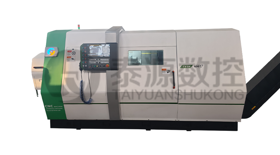 Model:TYSK-630T Drill Pipe, Joint & Coupling Lathe
The machine adopts a FANUC CNC system with stable processing accuracy and flexible programming functions to ensure that the processed parts meet strict industry standards. The high torque and heavy-load design can cope with long-term continuous work and has strong durability.
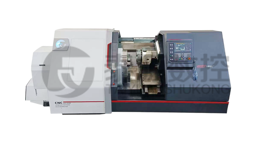 Model:TYSK-1355 Oil Pipe Processing Lathe
The machine adopts a FANUC CNC system with stable processing accuracy and flexible programming functions to ensure that the processed parts meet strict industry standards. The high torque and heavy-load design can cope with long-term continuous work and has strong durability.
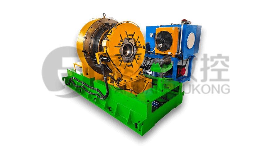 Series:TYSK-NKJ Screw-on machine/Casing and tubing coupling bucking unit
The machine uses a hydraulic motor, mechanical floating mechanism, and real-time torque detection, adapts to material bending, and prevents material deformation. Auxiliary machines are configured to help with semi-automation.
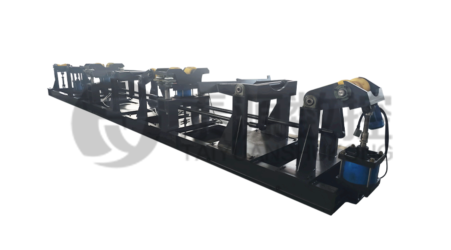 Long, heavy material solutions Automatic loading and unloading mechanism for pipe threading
The special flexible support mode can effectively reduce the influence of workpiece bending on processing and improve the yield. Strictly matching with our pipe threading lathe.
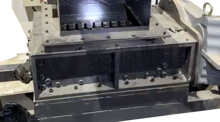 Modular Iron Chip Crusher High strength crusher for chip
The blades are made of high-strength materials and reasonably placed at the exit of the chip extractor to break the clump iron chips.Reduce the risk of rollback and improve waste frame utilization.
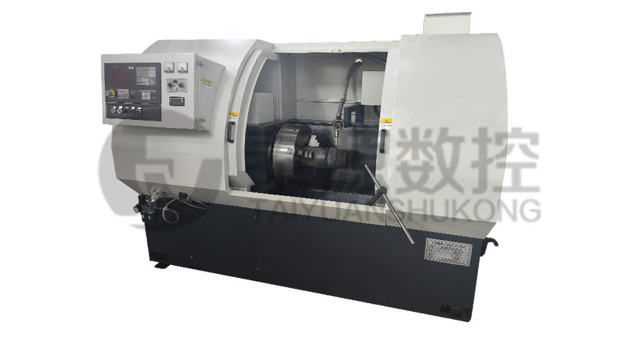 Series:TYSK-HB Semi-automatic wear-resistant band welder
Applicable to ARNCO 100XT, 200XT, 300XT. Support φ1.2-2.0 cored or solid wire surfacing welding.Can be equipped with single gun spray welding and double gun spray welding two ways. Support PLC or CNC system control.
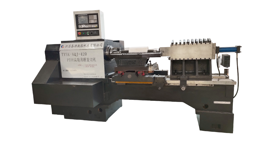 Model:TYSK-XQJ-550 Medium & Large PTFE Film Skiving Machine
Designed to process blanks with a maximum diameter of 550 mm and a maximum length of 1000 mm. We can also customize according to the needs of users. Friendly change speed and thickness with CNC.
