



 English
  عربى
عربى  中文简体
中文简体

Reminder information

Sep 09, 2026
Content
A bucking unit, sometimes called a coupling bucking machine or screw-on machine, applies controlled torque to make up or break out threaded casing and tubing connections. When it starts to fail, the first sign is usually not a lockup or a broken part. It is a torque graph that no longer matches the chart: the machine stops at the correct turn count, but the final torque is 10 percent lower than the previous joint, or the connection rotates a quarter turn after the spindle stops.
Many oilfield connections are specified to API 5B thread tolerances and made up to a connection-specific torque chart. The bucking unit is part of that measuring chain. The same pattern repeats across many shops: the bucking unit has slowly lost torque accuracy, clamping grip, or alignment. The pipe, coupling, and thread compound are within specification; the machine is the variable. This article maps the most common bucking unit problems to practical solutions, starting with diagnosis and moving through calibration, maintenance, and equipment selection. For a closer look at how these machines develop torque, read this explanation of torque output and make-up principles in a coupling bucking unit.
Experience on the floor usually points to five fault groups: torque transducer drift, clamping and insert wear, hydraulic pressure instability, spindle misalignment, and control or program errors. They are not always separate. A jaw that slips for one joint can create a torque spike that looks like a transducer fault, and a misaligned spindle can make every coupling start on an angle.
| Problem | What you see | Usual cause | First solution |
|---|---|---|---|
| Torque transducer drift | Final torque falls or rises between identical joints | Load-cell zero shift, damaged cable, incorrect gain | Re-zero at working temperature; verify with a traceable master cell |
| Jaw and insert wear | Pipe or coupling turns inside the jaws; scoring lines on the OD | Worn inserts, wrong die radius, low clamping pressure | Replace inserts; verify radius; set clamping pressure by pipe OD |
| Hydraulic pressure instability | Torque spikes or drops at the same pressure setting | Air in the circuit, worn relief valve, hot oil | Purge air; service relief valve; control oil temperature |
| Spindle misalignment | Coupling starts at an angle; first threads are damaged | Worn spindle taper, loose head, incorrect tram | Run a test bar; check taper contact; re-torque the assembly |
| Control or program error | Machine stops early or late; wrong turn count | Wrong thread number, residual offset, encoder drift | Verify the program; clear offsets; check encoder at both ends of travel |
Torque errors are the most expensive because they can hide a bad connection. A damaged transducer can read the target torque while the actual joint is under-torqued. The connection then leaves the station below the required make-up level. The best countermeasure is to record the full torque-versus-turn curve and compare its shape with the connection chart, not just the final number. Changes in thread compound also change friction, so the torque window is only valid for the compound listed on the chart.
Clamping faults are usually visible. Shiny marks around the pipe OD, rotation inside the jaws, or a pipe that starts to bow in the loader mean the insert radius or clamping pressure is wrong. Hydraulic faults can look like torque faults when the oil is cold, contaminated, or overheated. Alignment faults are the most dangerous because the damage happens in the first two threads; by the time the torque graph looks abnormal, the coupling is already cross-threaded.
Before replacing parts, run the bucking unit through a sequence that separates measuring errors from mechanical errors. The goal is to identify the first failure in the chain, not the part that breaks as a result.
A sudden spike at the end of the make-up cycle means the shoulder is contacting before the reference face is reached. A flat zone in the middle means the pipe may be slipping in the jaws. A smooth but increasingly steep curve usually points to thread compound compression, not thread damage. These curves can be compared directly because the bucking unit's encoder and torque transducer record the same data that the QC department needs.
Changeover is the moment when most bucking unit errors are introduced. A different casing size, a new coupling style, or a lower torque target can all look correct in the control screen while the physical setup is wrong. Making up one reference joint after the changeover catches these errors before production starts. The sequence is described in more detail in this guide to changeover procedures and torque control on a bucking unit lathe.
Preventive maintenance delivers the biggest impact when it treats the bucking unit as a measurement instrument, not just a hydraulic machine. A short daily checklist prevents most of the common problems from returning.
Oil viscosity changes with temperature, so calibrating a cold machine can introduce a systematic error into a warm production run. The torque transducer, cable, amplifier, and display should be verified with a master torque cell that is reserved for calibration only. A practical interval depends on the number of shifts and the severity of the work; many shops repeat a reference joint at the start of every shift and perform a full master-cell verification monthly.
Worn or incorrect jaw inserts are the most common cause of clamping-related bucking unit problems. The insert radius must match the actual pipe outside diameter, not a nominal size written in the job file. Thin-wall tubing will oval before the torque reading moves if the clamping pressure is set for a heavier casing string. Marking inserts by radius and keeping worn dies out of service is a low-cost way to avoid expensive thread damage.
Spindle misalignment is easy to ignore because it develops slowly. A test bar and a dial indicator will show whether the spindle nose is square with the clamping axis. The machine manufacturer's tolerance should be used instead of a visual check, because the first thread can be damaged by a fraction of a millimeter.
If the same problems reappear after a full maintenance cycle, the bucking unit may no longer have the stiffness, control resolution, or data logging needed for the connection mix in your shop. Selection should be based on torque range, spindle bore, clamping system, and the control functions that make changeover repeatable.
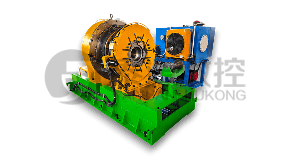
For shops that make up and break out casing and tubing couplings, the TYSKNKJ-100 screw-on machine casing and tubing coupling bucking unit is an example of a machine designed around controlled hydraulic torque and die-based clamping. It gives the operator a clear torque and turn readout, which is exactly what the diagnosis sequence needs.
For a broader comparison of machine types, read the guide to selecting a casing and tubing coupling bucking unit lathe before deciding between a stand-alone bucking unit, a combined threading and bucking machine, and a unit that will later be integrated into a production line.
Despite a correct diagnosis, some bucking unit failures leave damaged threads on otherwise usable tubulars. Scrapping every damaged pipe end is expensive, especially in small batches. A purpose-built oil pipe processing lathe can re-cut or restore the thread profile with the same precision expectations as the original machining. The TYSK1355 oil pipe processing lathe is one machine designed for this repair and re-machining work.
If the root problem is manual handling rather than torque accuracy, an automated coupling line removes the most variable part of the process: moving the pipe and coupling in and out of the bucking unit by hand. The coupling intelligent production line links make-up, inspection, and data recording so the torque curve is kept for each connection.
A bucking unit problem is solved when the machine can repeat the same torque and turn result within the connection tolerance. Start with calibration and changeover discipline. If the machine cannot hold the process after that, the next step should improve workholding, torque control, or material handling.
Related Products
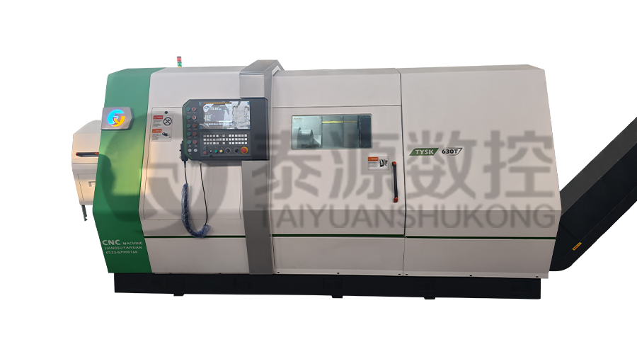 Model:TYSK-630T Drill Pipe, Joint & Coupling Lathe
The machine adopts a FANUC CNC system with stable processing accuracy and flexible programming functions to ensure that the processed parts meet strict industry standards. The high torque and heavy-load design can cope with long-term continuous work and has strong durability.
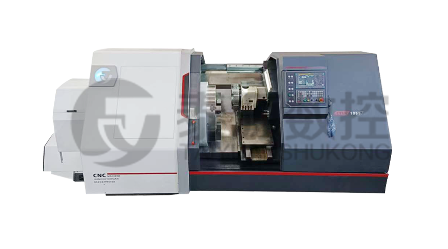 Model:TYSK-1355 Oil Pipe Processing Lathe
The machine adopts a FANUC CNC system with stable processing accuracy and flexible programming functions to ensure that the processed parts meet strict industry standards. The high torque and heavy-load design can cope with long-term continuous work and has strong durability.
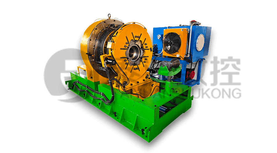 Series:TYSK-NKJ Screw-on machine/Casing and tubing coupling bucking unit
The machine uses a hydraulic motor, mechanical floating mechanism, and real-time torque detection, adapts to material bending, and prevents material deformation. Auxiliary machines are configured to help with semi-automation.
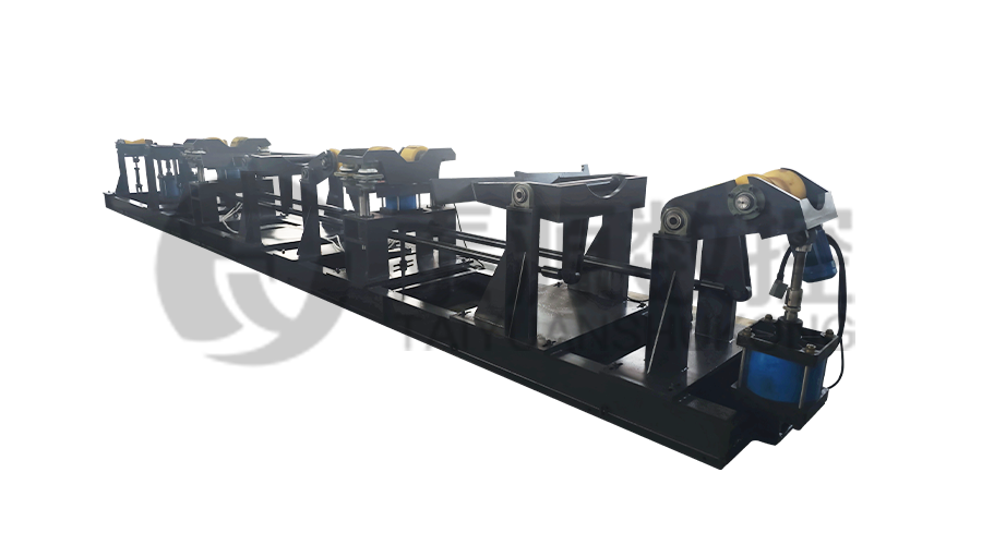 Long, heavy material solutions Automatic loading and unloading mechanism for pipe threading
The special flexible support mode can effectively reduce the influence of workpiece bending on processing and improve the yield. Strictly matching with our pipe threading lathe.
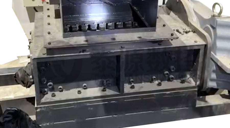 Modular Iron Chip Crusher High strength crusher for chip
The blades are made of high-strength materials and reasonably placed at the exit of the chip extractor to break the clump iron chips.Reduce the risk of rollback and improve waste frame utilization.
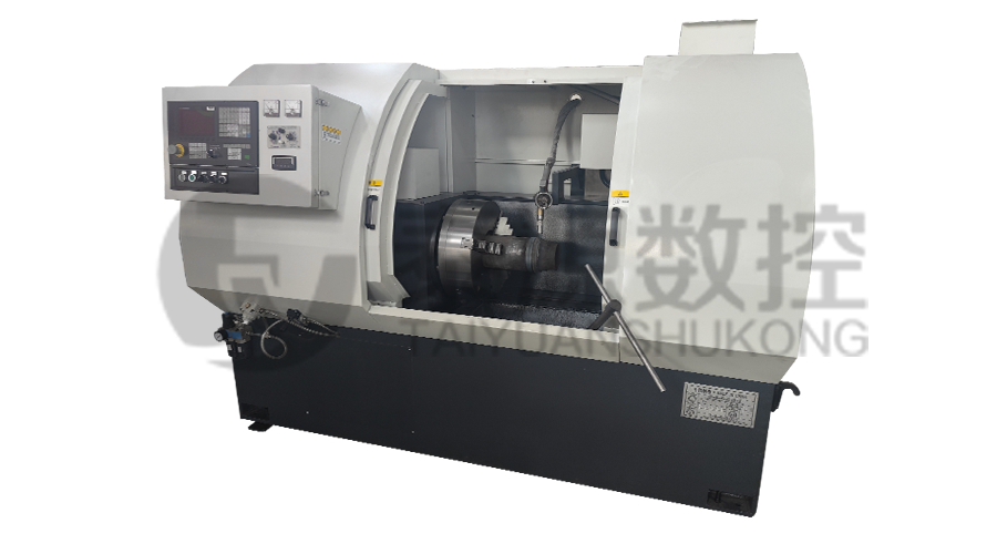 Series:TYSK-HB Semi-automatic wear-resistant band welder
Applicable to ARNCO 100XT, 200XT, 300XT. Support φ1.2-2.0 cored or solid wire surfacing welding.Can be equipped with single gun spray welding and double gun spray welding two ways. Support PLC or CNC system control.
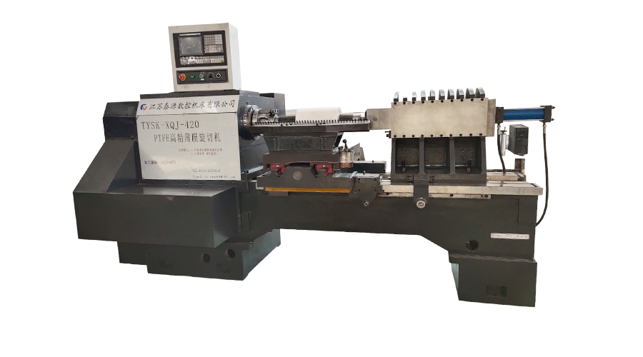 Model:TYSK-XQJ-550 Medium & Large PTFE Film Skiving Machine
Designed to process blanks with a maximum diameter of 550 mm and a maximum length of 1000 mm. We can also customize according to the needs of users. Friendly change speed and thickness with CNC.
