



 English
  عربى
عربى  中文简体
中文简体

Reminder information

Sep 03, 2026
Content
A casing connection that looks correct on the torque display can still be the weak link in a string. In a common field scenario, a 7-in. connection was made up at a stable torque reading, and only pressure testing later revealed a leak path. When the unit was inspected, the torque transducer was still connected, but the die inserts were uneven and a hydraulic valve was leaking. The screen was reporting a number; the machine was delivering something else.
Here is the conclusion: a casing and tubing bucking unit is a torque-control machine, not a general-purpose power wrench. The torque you apply to a connection is an outcome of the dies, hydraulic pressure, valve response, sensor condition, and alignment. Maintenance is the process that keeps those parts predictable. If you wait for a breakdown, you risk damaged threads, scrapped tubulars, and lost rig time.
Before you make up or break out the first joint, establish a consistent routine. A few minutes of checks at the start of a shift reduce the chance of damaging expensive casing and tubing.
Look at every die insert before the unit begins work. Check for cracked, rounded, or loaded dies. Scale, grease, or hardened thread compound on the gripping surface changes the contact pattern. Worn dies can let the pipe turn inside the jaws, which creates false torque readings and damages the pipe surface. Replace worn dies in sets, and match the die radius to the pipe diameter.
Start with a visual walk-around: hoses, fittings, cylinder rods, swivel joints, and the reservoir. A small leak can aerate the hydraulic oil and make torque output soft. Confirm oil level and pump pressure, then check the filters. If pressure builds slowly, look for pump cavitation or a blocked return filter.
Emergency stops, guards, and torque-limit switches must be checked while the machine is idle. Test the emergency stops at both the control panel and the remote pendant. If the unit sends data to a recording system, confirm that the joint number and torque values are being captured. This daily check takes minutes but prevents the much longer delay that follows a failed connection.
Lubrication is one of the most visible maintenance activities, but it is also one of the easiest to get wrong. Greasing only the fitting that is easy to reach is not a maintenance plan. A bucking unit has pivot pins, sliding surfaces, jaw carriers, rotary-head bearings, and gear sets that need the correct grease at the correct interval.
Keep hydraulic oil within the recommended viscosity range. High oil temperature makes pressure control less repeatable. Change return filters based on operating hours, and inspect oil samples if the unit works outdoors or in humid conditions. Water in hydraulic oil is one of the fastest ways to damage proportional valves and torque sensors.
If your bucking unit is built around a pipe-threading lathe platform, the changeover between make-up and cutting modes changes the way power is transmitted. Operators sometimes assume that one lubrication schedule covers both functions, but the bucking unit lathe versatility and torque control changeover can expose different bearing loads and valve response requirements. Treat the bucking torque path as a separate maintenance zone.
Torque accuracy is the main reason to maintain a bucking unit. Pressure transducers, torque sensors, and recording channels can drift over time. Shock loads, cable flex, temperature, and changes in hydraulic oil all shift the relationship between pressure and actual torque. A unit that was accurate six months ago may now be outside the tolerance defined in your operating procedure.
Use a calibrated torque transducer or a test joint to verify the unit’s readout. Record actual torque at several setpoints, including the low end and the high end of your working range. If the reading differs by more than the allowed tolerance, stop production and recalibrate. Do not simply apply a percentage offset for the rest of the shift; that hides a failing sensor instead of fixing it.
This is not a theoretical concern. The way pressure becomes torque depends on valve behavior, hydraulic oil condition, and mechanical friction. The technical principles of powerful torque output explain why torque repeatability must be verified rather than assumed.
If your connection process uses torque-turn or angular control, check the rotation sensor and encoder. A loose encoder mount or a slipping coupling will produce false angle readings. The best torque value in the world is useless if the system thinks the connection has turned 30 degrees when it has only turned 10.
Misalignment is one of the most damaging problems on a bucking unit. If the gripping jaws do not hold the pin and coupling on the same centerline, the threads engage at an angle and are damaged before torque can build. Alignment issues often show up as cross-threading, high or low torque readings, and unusual metal particles in the wash bin.
Check the die-carrier path and the rotary-head bearing for play. Use a dial indicator to measure axial and radial movement, then compare the readings with the machine manual. Inspect the torque arm or reaction system as well; backlash in this area appears on the connection as inconsistent torque. If the drive uses keys, splines, or gear teeth, examine them for wear.
Excessive heat in the rotary head usually points to a bearing or lubrication problem. Listen for rumble, knocking, or irregular rotation during make-up. A bucking unit should run smoothly. If the rotation becomes uneven, a guard may be rubbing, a bearing may be failing, or the backup jaws may be worn. Stop and repair before the next joint.
The table below summarizes a practical maintenance plan for a casing and tubing bucking unit. Use it as a starting point, and add the manufacturer’s specific limits, torque values, and calibration intervals to the same schedule.
| Interval | Inspection Area | Maintenance Action | Watch For |
|---|---|---|---|
| Daily | Die inserts, jaw faces, hydraulic reservoir, emergency stop | Remove debris from die inserts, confirm oil level, verify pressure, test emergency stop | Uneven die wear, low oil level, slow pressure recovery, loose guards |
| Weekly | Grease points, torque readout, die wear | Grease exposed pivots and slides, run a test joint at a known torque setpoint, inspect die inserts | Dry fittings, torque error outside allowed tolerance, cracked or rounded dies |
| Monthly | Hydraulic filters, rotary-head movement, sensor wiring | Change return filter if due, check bearing play with a dial indicator, inspect sensor cables and connectors | Blocked filters, axial or radial play above the manual limit, damaged wiring |
| Quarterly | Oil condition, heat exchanger, electrical connections | Sample hydraulic oil for water and contamination, clean cooler fins, check electrical terminations | Cloudy oil, overheated reservoir, loose connectors, corrosion |
| Annually | Full hydraulic system, torque sensor, rotary-head alignment | Replace oil or run oil analysis, renew seals, verify torque sensor with a certified transducer, check alignment | Excessive wear, calibration drift outside operating tolerance, rotary-head misalignment |
Do not wait for a failed connection to justify maintenance. Most of the items above are measurable and inexpensive to correct when found early. A small investment in inspection time protects a very expensive piece of the string.
When a bucking unit begins to behave differently, stop and identify the cause before continuing production. The most common problems are simple to diagnose if you check the mechanical and hydraulic systems in order.
Train operators to identify these warning signs early. If the torque value flickers, the rotary head makes a new noise, or the dies do not grip evenly, stop the unit and call maintenance. A short pause is far cheaper than a damaged connection.
Maintenance records matter even after the job is finished. Keep a log for torque verification, sensor calibration, oil changes, and die insert changes. The log should show dates, equipment hours, readings, and the name of the person who performed the work. If a connection is questioned later, that record gives you traceability and helps you decide whether the unit was performing within limits.
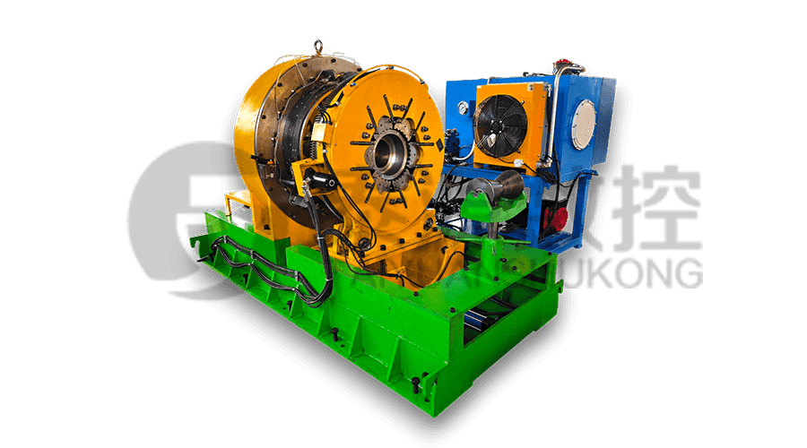
When it is time to purchase or replace equipment, serviceability should be part of the comparison. Ask about sensor access, die insert change time, and whether the rotary-head carrier can be inspected without removing the main frame. The TYSKNKJ-100 casing and tubing bucking unit is an example of a machine designed around these service considerations, with attention to repeatable torque control and accessible maintenance points.
Before selecting a new unit, review how to choose a screwed-on machine for your torque range and tubular sizes. Use the same care in selecting spare parts, calibration support, and operator training that you use in selecting the machine itself.
Set the schedule, follow it, and record it. Clean it. Lubricate it. Align it. Calibrate it. A well-maintained casing and tubing bucking unit is not only safer to operate; it is the best protection you can build into every connection.
Related Products
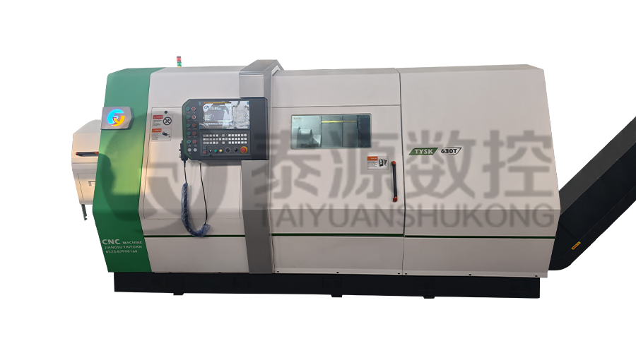 Model:TYSK-630T Drill Pipe, Joint & Coupling Lathe
The machine adopts a FANUC CNC system with stable processing accuracy and flexible programming functions to ensure that the processed parts meet strict industry standards. The high torque and heavy-load design can cope with long-term continuous work and has strong durability.
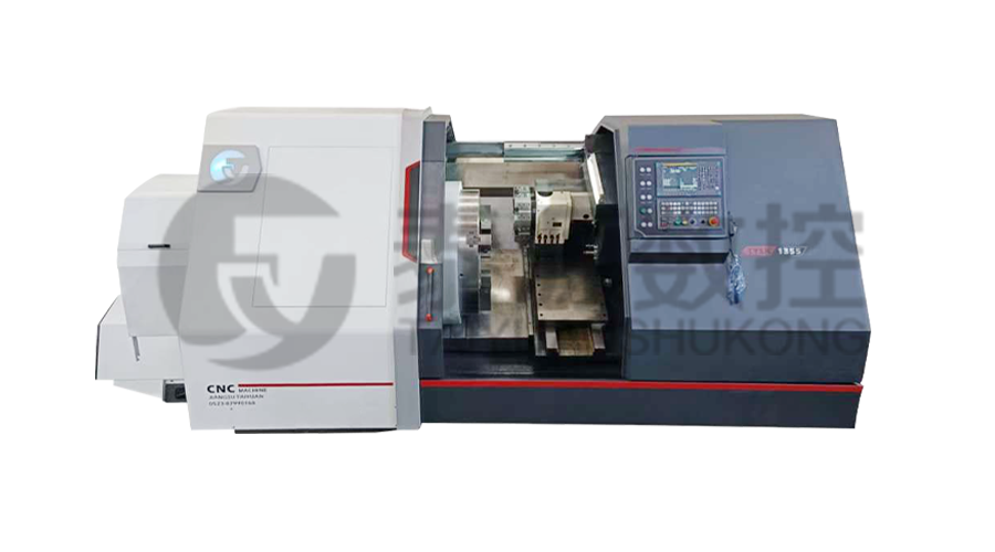 Model:TYSK-1355 Oil Pipe Processing Lathe
The machine adopts a FANUC CNC system with stable processing accuracy and flexible programming functions to ensure that the processed parts meet strict industry standards. The high torque and heavy-load design can cope with long-term continuous work and has strong durability.
Series:TYSK-NKJ Screw-on machine/Casing and tubing coupling bucking unit
The machine uses a hydraulic motor, mechanical floating mechanism, and real-time torque detection, adapts to material bending, and prevents material deformation. Auxiliary machines are configured to help with semi-automation.
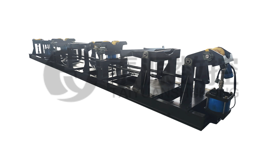 Long, heavy material solutions Automatic loading and unloading mechanism for pipe threading
The special flexible support mode can effectively reduce the influence of workpiece bending on processing and improve the yield. Strictly matching with our pipe threading lathe.
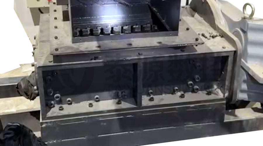 Modular Iron Chip Crusher High strength crusher for chip
The blades are made of high-strength materials and reasonably placed at the exit of the chip extractor to break the clump iron chips.Reduce the risk of rollback and improve waste frame utilization.
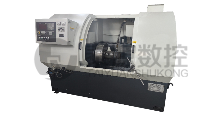 Series:TYSK-HB Semi-automatic wear-resistant band welder
Applicable to ARNCO 100XT, 200XT, 300XT. Support φ1.2-2.0 cored or solid wire surfacing welding.Can be equipped with single gun spray welding and double gun spray welding two ways. Support PLC or CNC system control.
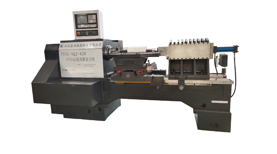 Model:TYSK-XQJ-550 Medium & Large PTFE Film Skiving Machine
Designed to process blanks with a maximum diameter of 550 mm and a maximum length of 1000 mm. We can also customize according to the needs of users. Friendly change speed and thickness with CNC.
