



 English
  عربى
عربى  中文简体
中文简体

Reminder information

Sep 04, 2026
Content
A casing connection that fails during makeup is rarely an accident. It is the result of decisions made long before the threads first touch. For anyone who operates or buys bucking equipment, the most reliable predictor of field performance is how the machine was built. The bucking unit manufacturing process determines torque accuracy, repeatability, and ultimately whether the unit protects premium connections or damages them.
A bucking unit, also called a casing and tubing coupling bucking unit or screw-on machine, makes up and breaks out threaded connections on casing, tubing, and drill pipe. During makeup, a spinner brings the connection together quickly, and a hydraulic wrench applies controlled torque that seats the threads to the value specified for that connection. During breakout, the same machine applies controlled reverse torque to separate the connection without galling or distorting the thread profile.
The word controlled is what separates an industrial-grade machine from a simple power wrench. Makeup torque is a calculated value based on thread geometry, thread compound, and service loads. If the machine cannot hold torque within a narrow band, the connection can leak or fail downhole no matter how good the pipe is. This is why the manufacturing process is so closely tied to operational performance. Studying how manufacturers achieve powerful torque output without mechanical shock is a practical way to compare designs before purchase.
Bucking unit manufacturing follows a disciplined sequence, because final performance depends as much on assembly quality as on component quality. In a typical plant, the build proceeds in this order:
Each stage builds on the previous one. A misaligned spindle bore cannot be corrected in software, and an unstable hydraulic circuit will produce unreliable torque readings no matter how accurate the transducer is.
The frame carries the full reaction torque of the wrench. On large casing connections, a unit can generate tens of thousands of newton-meters, and the frame deflects slightly under that load. If the deflection is not uniform, the wrench jaws lose alignment with the connection axis. Welding is the main source of risk, because residual welding stress can distort the frame after machining. Serious manufacturers stress-relieve the welded frame, then machine bearing seats and mounting faces in a single setup so that every critical axis shares one reference geometry.
The torque train is the mechanical path from the hydraulic motor to the connection: gearbox, spindle, and torque transducer. Transducer mounting matters more than most buyers realize. Direct in-line torque measurement captures the actual torque applied to the connection, while indirect systems infer torque from hydraulic pressure and lose accuracy as seals wear and oil temperature changes. During assembly, manufacturers verify gear meshing, bearing preload, and backlash. Excessive backlash causes torque spikes at the moment of thread contact, which is exactly when the thread surface is most vulnerable.
The wrench jaws and the spinner work as one system, and clamping force must stay consistent from the first connection to the last of the shift. Jaw slip during makeup generates heat and damages the pipe surface. Pressure-compensated pump controls, correctly sized accumulators, and hardened jaw inserts indicate that the hydraulic system was designed for continuous cycling rather than occasional light-duty use.
The control system translates torque curves into machine behavior. Modern units store connection-specific torque programs and reduce speed as torque approaches the target, finishing the last degrees of rotation at a creep speed. Calibration is part of the manufacturing process, not an afterthought. The torque transducer should be verified against a traceable reference, and the machine should ship with a calibration certificate.
End users rarely see the acceptance criteria that a bucking unit must meet before it leaves the factory. These targets are a useful baseline for evaluating what a manufacturer is willing to guarantee.
| Parameter | Typical acceptance target | Why it matters |
|---|---|---|
| Torque accuracy | ±1% or better of set value | Prevents under- or over-makeup of connections |
| Spindle bore concentricity | 0.05 mm TIR or less | Keeps jaws aligned with the connection axis |
| Torque transducer mounting | In-line, direct measurement | Maintains accuracy despite oil temperature and seal wear |
| Clamping force repeatability | ±2% or better | Prevents jaw slip and surface damage |
| Spinner speed control | Variable speed with creep function | Avoids impact loads at thread contact |
| Hydraulic leak rating | No external leakage at rated pressure | Ensures stable torque and safe operation |
These values are a useful baseline rather than a universal specification, but they illustrate what disciplined manufacturing targets look like. A unit that meets them handles repetitive make-and-break cycles with consistent results. A unit that does not will show up in the field as galling, connection leaks, and premature thread wear.
Before delivery, a bucking unit should undergo factory acceptance testing that reflects the real work cycle. The hydraulic system is pressure-tested, the wrench is cycled at full rated torque, and torque accuracy is checked at multiple points across the operating range. Because casing and tubing connections fall under standards such as API 5CT and API 5B, many suppliers must also demonstrate that their equipment handles the torque values and thread forms those standards require.
Request the calibration certificate and the factory acceptance report, not just a brochure. When a manufacturer cannot document torque traceability, field performance becomes a gamble. For a deeper look at the regulatory side, review API 5CT bucking lathe compliance requirements before finalizing your specification.
The consequences of manufacturing shortcuts appear in predictable places:
The most visible sign of a good manufacturing process is boring predictability: the same torque, the same speed curve, and the same result on every connection.
Understanding the manufacturing process makes it easier to ask the right questions before signing a purchase order:
At the equipment level, a practical option for casing and tubing work is the TYSKNKJ-100 series bucking unit for casing and tubing, which is built for controlled makeup and breakout torque in oilfield tubular processing.
In a complete coupling plant, an oil pipe processing lathe for the threading operation upstream must hold thread geometry within tolerance before the bucking unit ever sees the connection. Beyond the machines themselves, a coupling intelligent production line that links machining, bucking, and inspection into one flow prevents the bottleneck that a single good machine cannot fix.
The bucking unit manufacturing process is not a list of parts; it is a sequence of controlled decisions about alignment, torque, calibration, and verification. Buyers who understand those decisions can tell the difference between a machine that protects premium connections and one that quietly damages them. That difference shows up in every thread, every joint, and every well it reaches.
Related Products
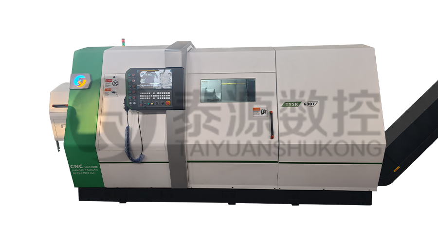 Model:TYSK-630T Drill Pipe, Joint & Coupling Lathe
The machine adopts a FANUC CNC system with stable processing accuracy and flexible programming functions to ensure that the processed parts meet strict industry standards. The high torque and heavy-load design can cope with long-term continuous work and has strong durability.
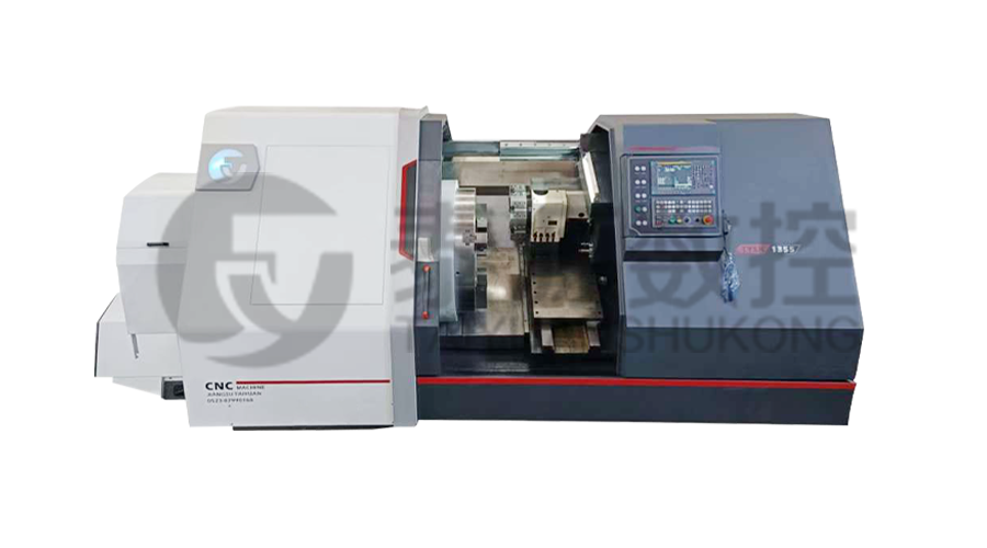 Model:TYSK-1355 Oil Pipe Processing Lathe
The machine adopts a FANUC CNC system with stable processing accuracy and flexible programming functions to ensure that the processed parts meet strict industry standards. The high torque and heavy-load design can cope with long-term continuous work and has strong durability.
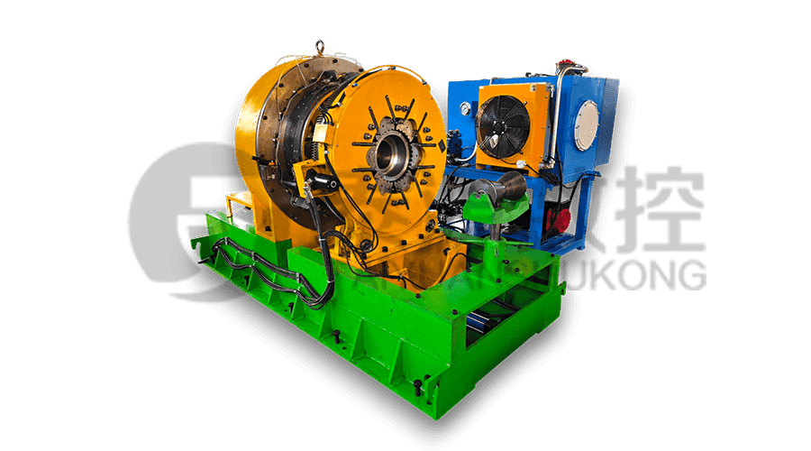 Series:TYSK-NKJ Screw-on machine/Casing and tubing coupling bucking unit
The machine uses a hydraulic motor, mechanical floating mechanism, and real-time torque detection, adapts to material bending, and prevents material deformation. Auxiliary machines are configured to help with semi-automation.
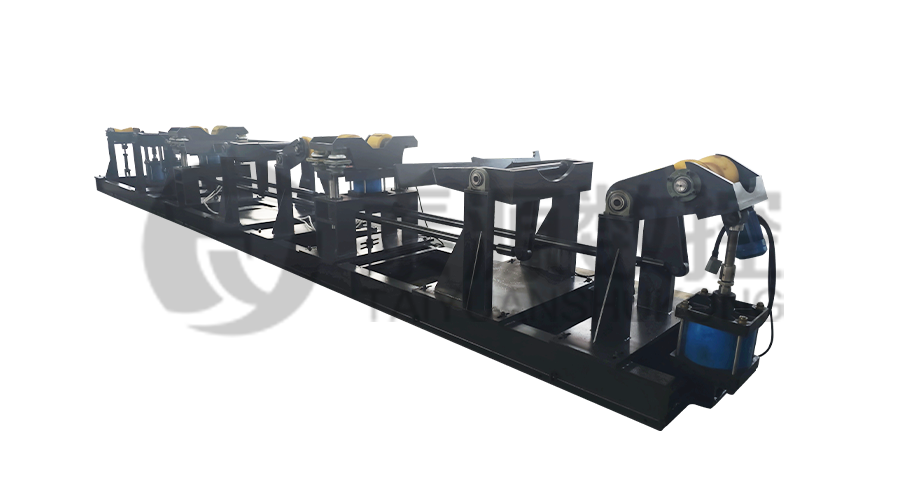 Long, heavy material solutions Automatic loading and unloading mechanism for pipe threading
The special flexible support mode can effectively reduce the influence of workpiece bending on processing and improve the yield. Strictly matching with our pipe threading lathe.
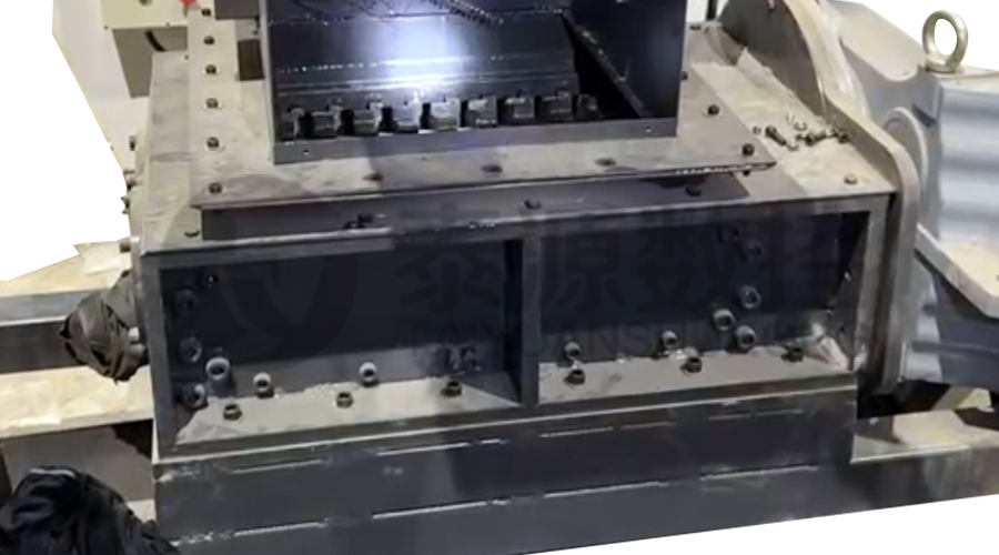 Modular Iron Chip Crusher High strength crusher for chip
The blades are made of high-strength materials and reasonably placed at the exit of the chip extractor to break the clump iron chips.Reduce the risk of rollback and improve waste frame utilization.
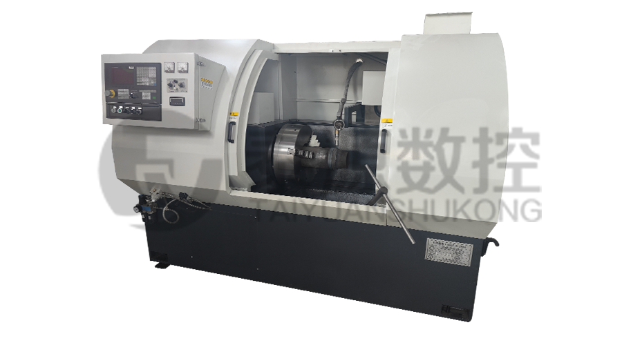 Series:TYSK-HB Semi-automatic wear-resistant band welder
Applicable to ARNCO 100XT, 200XT, 300XT. Support φ1.2-2.0 cored or solid wire surfacing welding.Can be equipped with single gun spray welding and double gun spray welding two ways. Support PLC or CNC system control.
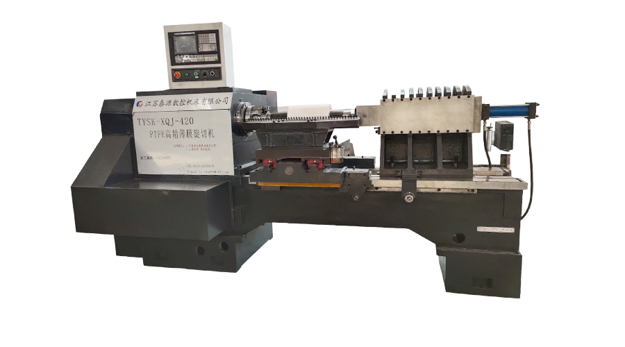 Model:TYSK-XQJ-550 Medium & Large PTFE Film Skiving Machine
Designed to process blanks with a maximum diameter of 550 mm and a maximum length of 1000 mm. We can also customize according to the needs of users. Friendly change speed and thickness with CNC.
