



 English
  عربى
عربى  中文简体
中文简体

Reminder information

Aug 19, 2026
Content
Before a coupling enters service, one machine has the final word on how well the threads are assembled: the bucking unit. It tightens a coupling onto casing or tubing at a controlled torque, and when that torque is wrong the failure often appears only after the connection is in service. The main components of a bucking unit define its accuracy, its service life, and its operating cost, and each deserves scrutiny before a purchase.
A bucking unit is simpler than a threading lathe in daily maintenance, but the forces involved are large and the acceptable error is small. A unit that delivers torque out of specification by a few percent can create damage that is invisible at the time and expensive later. The table below lists the main component groups; the sections that follow explain what each does and how it affects production.
| Component group | Primary function | Why it matters |
|---|---|---|
| Frame and torque reaction structure | Absorbs reaction torque and keeps working elements aligned | Controls torque consistency and machine life |
| Torque head | Grips and rotates the pipe or coupling | Sets maximum torque and pipe size capacity |
| Backup tong | Holds the opposite end of the connection | Prevents slippage and thread damage |
| Hydraulic power unit | Supplies pressure and flow for rotation and clamping | Determines peak output and shift-long stability |
| Torque measurement and control | Measures and regulates makeup torque | Defines accuracy and compliance |
| Electrical controls and HMI | Runs the cycle, stores recipes, logs data | Affects safety, traceability, and changeover time |
| Auxiliary systems | Dope application, lubrication, cooling, safety | Drive uptime and connection quality |
A bucking unit generates torque, and the structure that holds it absorbs an equal and opposite reaction. If the frame is not rigid enough, the alignment between the torque head and the backup tong changes during the cycle, and the torque recorded by the control system no longer matches what the threads actually experience.
Well-built units use a heavy cast iron base or a welded steel fabrication with internal ribs and stress-relieved sections. The critical geometry is the axis between the torque head and the backup tong: they must stay concentric under maximum load. A bolted frame that can loosen over time appears as declining torque accuracy, so a one-piece or precision-machined structure is preferable. When comparing machines, frame mass and stiffness tell more than rated torque alone.
The torque head grips one member of the connection and rotates it. Its three main parts are the spindle, the drive train, and the clamping jaws.
The spindle is a large-bore shaft carried by bearings that handle radial and axial loads. Its bore diameter sets the largest outside diameter of pipe or coupling that can pass through the head, so spindle bore is the first specification to compare against your product range. Behind the spindle, a hydraulic motor and reduction gearbox multiply torque to the rated value.
Gripping is where machine quality becomes visible. Hydraulically actuated jaws or slip-type dies close on the work piece and transmit torque into the connection. Jaw inserts are matched to the pipe material; a worn or mismatched insert allows slippage, and a slipping jaw is the fastest way to score a premium thread. Clamping force must also be limited so the grip does not crush thin-walled tubing.
The backup tong holds the opposite side of the connection while the torque head rotates. In a casing and tubing bucking unit, it uses a full-circle or segmented gripping assembly driven by hydraulic clamping cylinders.
The backup grip must be at least as strong as the machine's maximum torque, because any slippage here means the pipe spins instead of the connection tightening. The jaws must also distribute force evenly so they do not mark the pipe body or ovalize thin-wall tubing, which is why jaw packages are matched to the outside diameter and wall thickness of each pipe size.
The hydraulic power unit supplies energy for both rotation and clamping: electric motor, pump, reservoir, control manifolds, pressure relief valves, and accumulators.
Accumulators matter because peak torque is intermittent. They store energy during idle time and release it during a makeup cycle, letting a smaller pump deliver the same peak torque. Valve tuning controls how smoothly torque ramps up; an abrupt step can shock the threads and cause galling.
Heat management is a production issue. Continuous running raises oil temperature, which thins the oil and shifts pressure readings. A correctly sized oil cooler and reservoir keep the system in a stable temperature band, and that stability makes the torque control loop more consistent at the end of a shift.
Torque measurement separates a powerful machine from a precise one. Direct systems use a load cell or torque sensor on the drive train; indirect systems calculate torque from hydraulic pressure at the motor. Direct sensing is more accurate because it excludes friction and temperature effects in the hydraulic circuit, and it is preferred when documented torque values are required.
The control loop manages makeup as a sequence: contact, ramping torque, final hold, and release. Some operations need torque-only control; others need torque-and-turn control, where the system tracks rotation angle and can detect cross-threading. Good control holds the upper and lower torque limits consistently while keeping the cycle fast enough for the line rate.
For oilfield tubulars, documented performance is part of product acceptance. Shops running API 5CT casing and tubing typically review the API 5CT compliance requirements before accepting a unit's torque records.
When a schedule moves between casing sizes, the unit's torque control and changeover behavior determines how much downtime each size change costs.
A PLC runs the cycle: clamping, positioning, torque ramp, completion, and release. The HMI shows target torque, achieved torque, cycle counts, and alarms, and stores recipes for different pipe sizes. Entering a recipe instead of turning a manual valve removes most operator-dependent variation from connection quality.
The electrical system also carries the safety function: two-hand start, interlocked guards, emergency stop, and automatic shutdown when a torque limit is exceeded. Data logging and network connectivity let each joint be traced to its makeup parameters, which is increasingly expected in quality audits.
The auxiliary components do not produce torque, but they decide whether the machine runs a full shift without interruption.
Thread compound protects the thread surface and controls friction. Automatic dope applicators meter a reproducible amount per joint, while manual application varies from operator to operator: too much compound can allow overtightening, and too little raises the risk of galling.
The main bearings, gearbox, and slide surfaces need a continuous oil supply. Loss of lubrication is the most common cause of premature bearing failure in these machines and is usually preventable. The cooling system keeps oil temperature inside the window the control loop expects.
Interlocked guards and torque-trip mechanisms stop the machine after an abnormal event. In higher-throughput plants, the bucking unit connects to conveyors and loading equipment so pipes move through automatically. In that arrangement, the station becomes one element of a coupling intelligent production line that coordinates handling, inspection, and tightening, and its PLC handshake and cycle-time match matter as much as its torque rating.
The component groups reduce to a checklist. Rated torque needs a margin above your heaviest connection. Spindle bore must clear the largest coupling. Torque measurement should be direct and documented for API-controlled work. Changeover speed depends on jaws and recipe storage. Maintenance access determines how long repairs take.
These are the criteria to bring into any comparison. The casing and tubing coupling bucking unit lathe selection guide explains how to match them to a specific production program, so the decision is based on measurable capability rather than nameplate numbers.
One example of these decisions applied in practice is the TYSKNKJ-100 series casing and tubing coupling bucking unit, a screw-on machine built around controlled torque ramp, secure gripping, and quick changeover. It is intended for plants that process casing and tubing in production volumes and need the unit to hold tolerances across a full shift.
A bucking unit does one simple-sounding job — make up or break out a threaded connection at a controlled torque — and every main component exists to make that job repeatable. The frame absorbs the forces, the torque head and backup tong grip and rotate, the hydraulic unit supplies power, the control system ensures accuracy, and the electrical and auxiliary systems keep the operation safe. A weakness in any component eventually shows up as scrap, rework, or unplanned maintenance.
In most shops, the bucking unit is planned together with the threading machine: the lathe cuts the thread, and the bucking unit proves the parts assemble correctly. A drill pipe joint coupling lathe covers the cutting side of the same product range, and the two machines should be specified around the same pipe outside diameter, connection type, and production rate.
Related Products
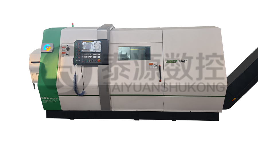 Model:TYSK-630T Drill Pipe, Joint & Coupling Lathe
The machine adopts a FANUC CNC system with stable processing accuracy and flexible programming functions to ensure that the processed parts meet strict industry standards. The high torque and heavy-load design can cope with long-term continuous work and has strong durability.
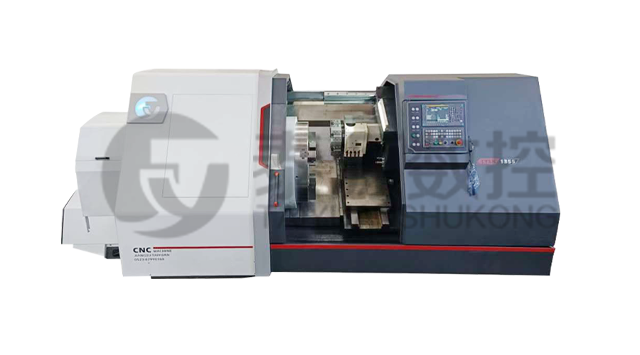 Model:TYSK-1355 Oil Pipe Processing Lathe
The machine adopts a FANUC CNC system with stable processing accuracy and flexible programming functions to ensure that the processed parts meet strict industry standards. The high torque and heavy-load design can cope with long-term continuous work and has strong durability.
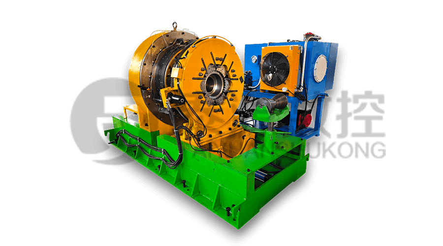 Series:TYSK-NKJ Screw-on machine/Casing and tubing coupling bucking unit
The machine uses a hydraulic motor, mechanical floating mechanism, and real-time torque detection, adapts to material bending, and prevents material deformation. Auxiliary machines are configured to help with semi-automation.
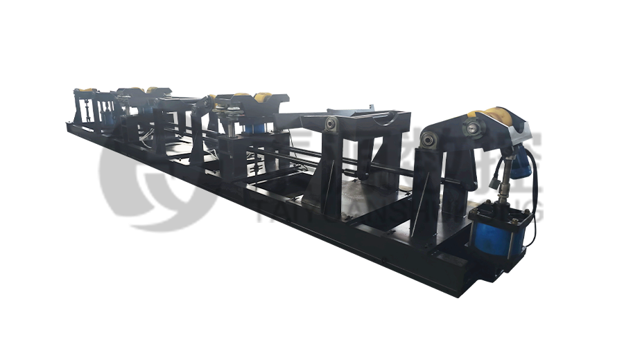 Long, heavy material solutions Automatic loading and unloading mechanism for pipe threading
The special flexible support mode can effectively reduce the influence of workpiece bending on processing and improve the yield. Strictly matching with our pipe threading lathe.
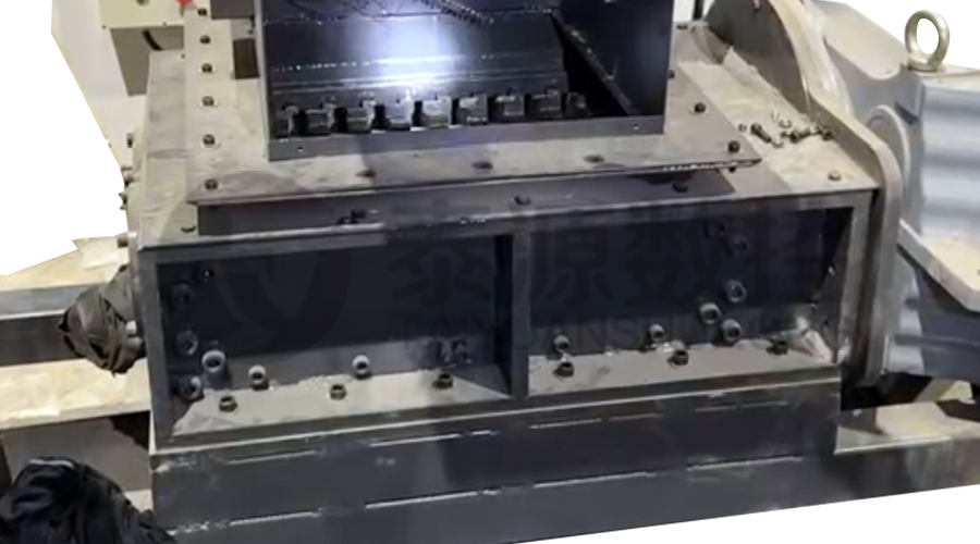 Modular Iron Chip Crusher High strength crusher for chip
The blades are made of high-strength materials and reasonably placed at the exit of the chip extractor to break the clump iron chips.Reduce the risk of rollback and improve waste frame utilization.
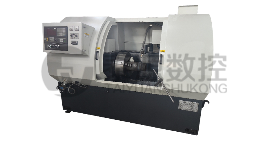 Series:TYSK-HB Semi-automatic wear-resistant band welder
Applicable to ARNCO 100XT, 200XT, 300XT. Support φ1.2-2.0 cored or solid wire surfacing welding.Can be equipped with single gun spray welding and double gun spray welding two ways. Support PLC or CNC system control.
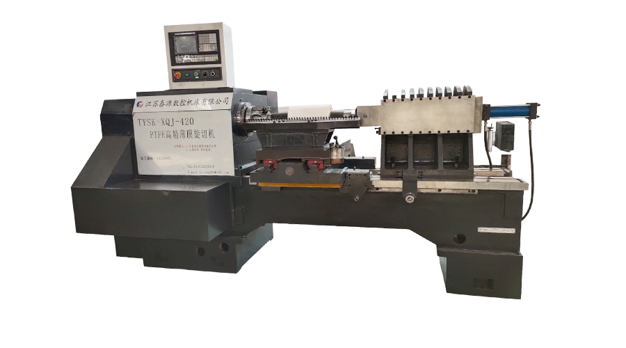 Model:TYSK-XQJ-550 Medium & Large PTFE Film Skiving Machine
Designed to process blanks with a maximum diameter of 550 mm and a maximum length of 1000 mm. We can also customize according to the needs of users. Friendly change speed and thickness with CNC.
